


3
INSTINST
INSTINST
INST
ALLAALLA
ALLAALLA
ALLA
TIONTION
TIONTION
TION
RULES FOR SAFE INSTALLATIONRULES FOR SAFE INSTALLATION
RULES FOR SAFE INSTALLATIONRULES FOR SAFE INSTALLATION
RULES FOR SAFE INSTALLATION
AND OPERATIONAND OPERATION
AND OPERATIONAND OPERATION
AND OPERATION
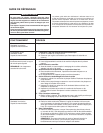
1. Read the Owners Manual and the Rules for Safe
Operation carefully. Failure to follow these rules and
instructions could cause a malfunction of filter or
unsatisfactory service.
2. Follow a regular service and maintenance schedule for
efficient operation.
PLACEMENTPLACEMENT
PLACEMENTPLACEMENT
PLACEMENT
The installer must be qualified to make approved electrical
connections and a safe ceiling installation with attention to the
best placement as shown in the following drawings.
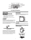
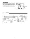
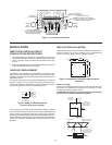
The electronic air cleaner should be mounted in the center of the
room. Air is drawn through the bottom grille and discharged
through the four side grilles. Divide larger rooms into sections
and use a unit in each section (Fig. 2).
Check existing air circulation in the room. The air cleaner should
be installed so that it aids the circulation already established.
When air flow patterns are not immediately apparent, observe
the smoke from a cigarette in various locations within the room.
Do not locate the air cleaner near a heating or air conditioning
intake or exhaust vent if it interferes with the air flow discharge
and return air to the heating or air conditioning unit.
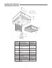
CEILING MOUNTCEILING MOUNT
CEILING MOUNTCEILING MOUNT
CEILING MOUNT
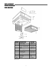
The air cleaner is mounted by suspending it from the building
structure above the suspended ceiling. The mounting holes are
spaced 21” and 15
3
/4” between centers (Fig. 3).
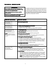
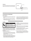
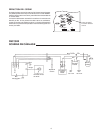
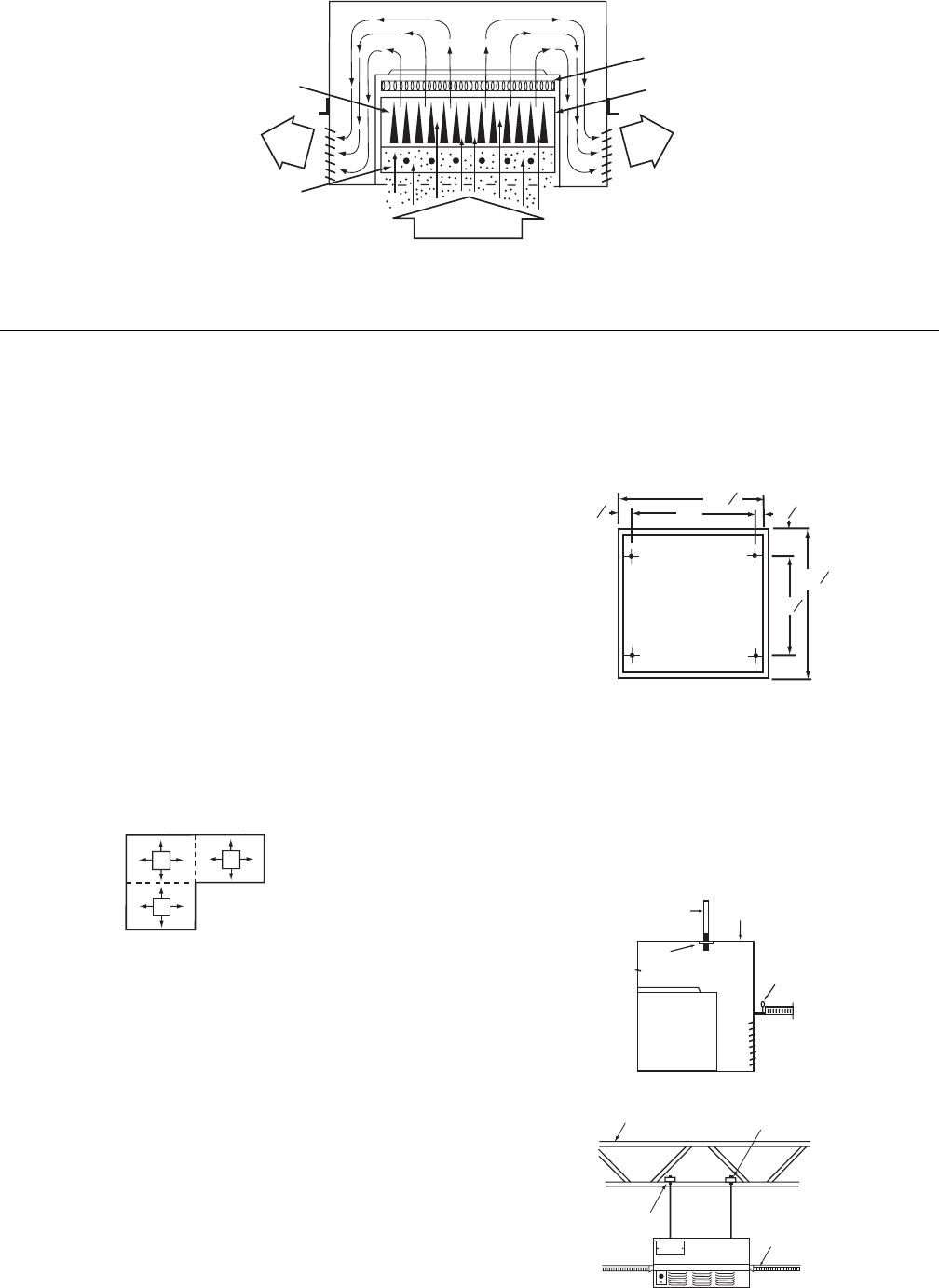
COLLECTING
PLATES
CLEAN
AIR
OUT
CLEAN
AIR
OUT
IONIZING SECTION
IONIZING WIRES GIVE DIRT
PARTICLES A POSITIVE CHARGE
CHARCOAL FILTER
REDUCES ODOR
COLLECTING SECTION
COLLECTOR PLATES ATTRACT
AND HOLD DIRT PARTICLES
LIKE A MAGNET
DIRTY
AIR IN
3
8
3
8
3
4
3
4
3
4
1
1
23
21
4
4
15
23
Mounting DetailMounting Detail
Mounting DetailMounting Detail
Mounting Detail
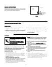
Select a mounting location where the structure above is strong
enough to support the weight of approximately 50 lbs (Fig.4 &
5).
CAUTION: Do not allow the unit to be supported by theCAUTION: Do not allow the unit to be supported by the
CAUTION: Do not allow the unit to be supported by theCAUTION: Do not allow the unit to be supported by the
CAUTION: Do not allow the unit to be supported by the
ceiling tile grid suspension.ceiling tile grid suspension.
ceiling tile grid suspension.ceiling tile grid suspension.
ceiling tile grid suspension.
3/8" DIA. STEEL
THREADED ROD
COVER
WELD NUT
CEILING GRID
(DO NOT USE
FOR SUPPORT)
CEILING GRID
(DO NOT USE
FOR SUPPORT)
2X4
ROOF SUPPORT JOIST
NUT & WASHER TOP AND BOTTOM
FIGFIG
FIGFIG
FIG
..
..
.
1 Illustr 1 Illustr
1 Illustr 1 Illustr
1 Illustr
aa
aa
a
tion oftion of
tion oftion of
tion of
Air Cleaning PrAir Cleaning Pr
Air Cleaning PrAir Cleaning Pr
Air Cleaning Pr
ocessocess
ocessocess
ocess
FIGFIG
FIGFIG
FIG
..
..
.
2 Mount the unit on the ceiling a 2 Mount the unit on the ceiling a
2 Mount the unit on the ceiling a 2 Mount the unit on the ceiling a
2 Mount the unit on the ceiling a
t the centert the center
t the centert the center
t the center
ofof
ofof
of
ar ar
ar ar
ar
ea to be cea to be c
ea to be cea to be c
ea to be c
leaned.leaned.
leaned.leaned.
leaned.
FIGFIG
FIGFIG
FIG
..
..
.
3 3
3 3
3
AA
AA
A
pprppr
pprppr
ppr
oo
oo
o
ximaxima
ximaxima
xima
te Installate Installa
te Installate Installa
te Installa
tion Dimensions in Inction Dimensions in Inc
tion Dimensions in Inction Dimensions in Inc
tion Dimensions in Inc
heshes
heshes
hes
FIGFIG
FIGFIG
FIG
..
..
.
4 4
4 4
4
FIGFIG
FIGFIG
FIG
..
..
.
5 5
5 5
5