


127237-UUM-A-0605
4 Unitary Products Group
FURNACE USER MAINTENANCE
Blower Care
Even with good filters properly in place, blower wheels and motors will
become dust laden after long months of operation. The entire blower
assembly should be inspected annually. If the motor and wheel are
heavily coated with dust, they can be brushed and cleaned with a vac-
uum cleaner. If the blower cannot be properly cleaned without removing
it from the furnace, then this service must be performed by a qualified
service agency.
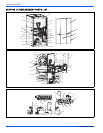
The blower can be serviced/removed through the blower access panel
on the inside of the furnace. If there is a combustion air pipe installed
inside the furnace, it may have to be removed to access the blower
access panel. After the combustion air pipe is removed, it is easy to
remove the inside blower access panel by removing the screws of the
access panel. Blower is now ready to be serviced through the opening.
If the blower has to be removed through the inside blower access panel,
then the top and bottom angles will have to be removed to slide the
blower out of the furnace.
Air Filters
The filters should be checked every 3 months. On new construction,
check the filters every week for the first four weeks and every three
weeks after that, especially if the indoor fan is running continuously.
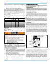
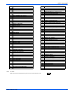
When replacing the filter(s), refer to Table 1 to be sure you install the
right size filter for your furnace. Dirty filters greatly restrict the flow of air
and may cause damage to the moving parts of the furnace. If the filters
become clogged the heat exchangers and blower motor could overheat
resulting in a potentially dangerous situation.
Never operate your furnace without a suitable air filter.
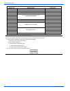
Use the following procedure to determine the filter size.
1. Measure the furnace width and use that measurement to deter-
mine the cabinet width.
• A 14-1/2” wide cabinet is a “A” cabinet.
• A 17-1/2” wide cabinet is a “B” cabinet.
• A 21” wide cabinet is a “C” cabinet.
• A 24-1/2” wide cabinet is a “D” cabinet.
2. Locate the cabinet size on Table 1 then determine whether you
have a bottom or side return air duct using the following method.
a. If the return air filter is on the left or right side of the furnace it
is a side return
b. If the air filter is on the bottom of the furnace then you have a
bottom return.
c. If the air filters are on the bottom and the side of the furnace
then you have a bottom and side return. You must replace
both air filters. Table 1 will indicate 2 filters by using brackets
with the number two (2).
d. If the air filters are on both sides of the furnace then you have
a two sided return. You must replace both air filters. Table 1
will indicate 2 filters by using brackets with the number two
(2).
3. After you determine the cabinet size and what return configuration
you have, look up the recommended filter size from Table 1.
Removing Filters
Most downflow furnaces have their filters located on the top of the fur-
nace in an external filter rack. To check filters you should:
1. Follow the instructions to turn off the appliance before servicing.
2. Filters are installed in the return air plenum above the blower
assembly. An “A” frame assembly supports the filters. Lift the filter
slightly and remove for service.
3. Follow the instructions “HOW TO CLEAN YOUR FURNACE’S FIL-
TER”.
4. Reverse the procedure to reinstall filters.
5. Follow the operating instructions to place appliance in operation.
Externally Mounted Air Filters
Some installations may have the air filter in a rack attached to the cas-
ing of the furnace or placed in the return air duct. You can gain access
to the filter by pulling on the door or unscrewing the retaining screw,
then slide the filter(s) out of its channel. Replace throw away filter(s)
with the same size new filter(s). Throw away filter(s) may be replaced
with cleanable filter(s) at this time. Cleanable filter(s) may be cleaned as
described in the manufacturer instructions or as described below and
then re-installed.
How to Clean your Filter
High-velocity filters may be cleaned with a vacuum cleaner or washed
with a garden hose. Be sure to shake off excess water and allow filter to
completely dry before re-installing the filter.
To replace the filter after cleaning you must do the following:
1. Slide filter into place.
2. Snap the door on or place the door in position and tighten the
retaining screws, if provided.
3. Make sure the door is secure to the end of the filter rack.
4. For filter grilles, place the filter into the grilles, close the grille cover
and tighten the retaining screw.
Every time the filters are changed the following items should be visually
inspected:
• Check combustion air and vent pipe for blockage or leakage.
• Check all components to be sure they are in good condition and
that there are no obvious signs of deterioration.
• Check the drain lines to make sure there are no cracks or leaks.
• Check for dirt or lint on any surfaces or on components. Do not try
to clean any of the surfaces or components. Cleaning of the fur-
nace and its components must be done by a qualified service pro-
fessional.
Before proceeding, be sure the area is well ventilated. Turn
the thermostat OFF. If the blower is running, wait until it
stops automatically. Turn OFF the gas and electrical power
supplies to the furnace. Check all metal parts and surfaces
to be sure they have cooled to room temperature before
you begin.
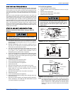
Make sure you DO NOT move the clip-on weight on the
indoor fan wheel when cleaning the wheel. This weight is
used to balance the wheel. Moving the weight will cause
the fan wheel to vibrate.
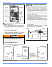
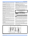
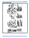
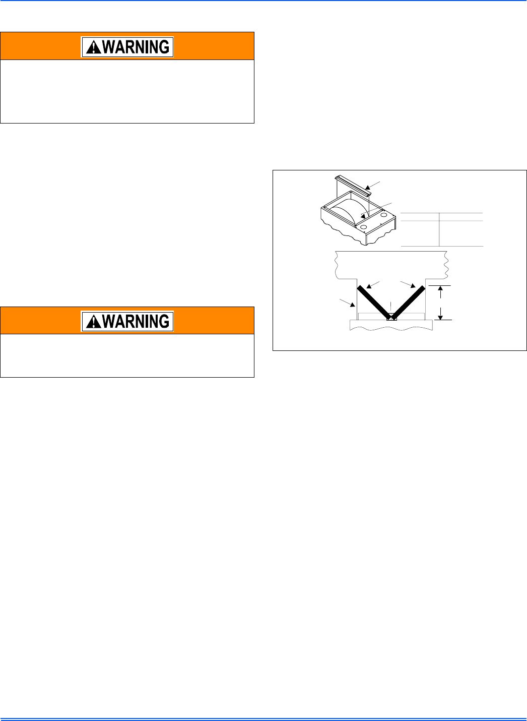
FIGURE 7: Filter Rack Assembly and Attachment
FILTER RACK
(factory supplied with some furnaces)
RACK AND FILTERS SECURED
INSIDE BLOWER SECTION
FOR SHIPMENT
DUCTWORK
FILTERS
BRANCH
DUCTS
FH
CROSS SECTION A-A
(with Plenum and filters)
FILTER
RACK
NOTE: FILTER ACCESSTHROUGH
DUCTWORK MUST BE PROVIDED
FOR REMOVALAND CLEANING
CASING SIZE
DIMENSION FH
14-1/2”
17-1/2”
21”
24-1/2”
13-1/4”
12-1/2”
11-1/2”
9-3/4”