


4
CONFIGURATIONCONFIGURATION
CONFIGURATIONCONFIGURATION
CONFIGURATION
Comfort-Set IIComfort-Set II
Comfort-Set IIComfort-Set II
Comfort-Set II
Single Stage ModelsSingle Stage Models
Single Stage ModelsSingle Stage Models
Single Stage Models: Verify jumper wire
W-22W-22
W-22W-22
W-22 on the back
of the thermostat (not the subbase) has been clipped.
Multi-stage and Heat Pump ModelsMulti-stage and Heat Pump Models
Multi-stage and Heat Pump ModelsMulti-stage and Heat Pump Models
Multi-stage and Heat Pump Models: Verify jumper wire
W-W-
W-W-
W-
1818
1818
18 on the back of the thermostat (not the subbase) has
been clipped.
Comfort-Set III/Comfort-Set 90/90 SeriesComfort-Set III/Comfort-Set 90/90 Series
Comfort-Set III/Comfort-Set 90/90 SeriesComfort-Set III/Comfort-Set 90/90 Series
Comfort-Set III/Comfort-Set 90/90 Series
Single Stage ModelsSingle Stage Models
Single Stage ModelsSingle Stage Models
Single Stage Models: Verify jumper wire
W-922W-922
W-922W-922
W-922 on the
back of the thermostat (not the subbase) has been clipped.
You must also enable the remote sensor option in the
Installation Instructions, Configuration Menu.
Multi-stage and Heat Pump ModelsMulti-stage and Heat Pump Models
Multi-stage and Heat Pump ModelsMulti-stage and Heat Pump Models
Multi-stage and Heat Pump Models: When installing a
remote sensor you must enable the remote sensor option in
the Installation Instructions, Installer Menu.
REMOTE SENSOR CALCULATED PRIORITY AVERAGEREMOTE SENSOR CALCULATED PRIORITY AVERAGE
REMOTE SENSOR CALCULATED PRIORITY AVERAGEREMOTE SENSOR CALCULATED PRIORITY AVERAGE
REMOTE SENSOR CALCULATED PRIORITY AVERAGE
1F93-380, 1F94-371, 1F95-371, 1F95-377, 1F95-3911F93-380, 1F94-371, 1F95-371, 1F95-377, 1F95-391
1F93-380, 1F94-371, 1F95-371, 1F95-377, 1F95-3911F93-380, 1F94-371, 1F95-371, 1F95-377, 1F95-391
1F93-380, 1F94-371, 1F95-371, 1F95-377, 1F95-391
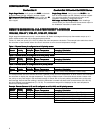
Single stage thermostats accept only 1 remote sensor. 90 Series multi-stage and heat pump thermostats accept up to 3
indoor remote sensors and can be assigned sensor priorities.
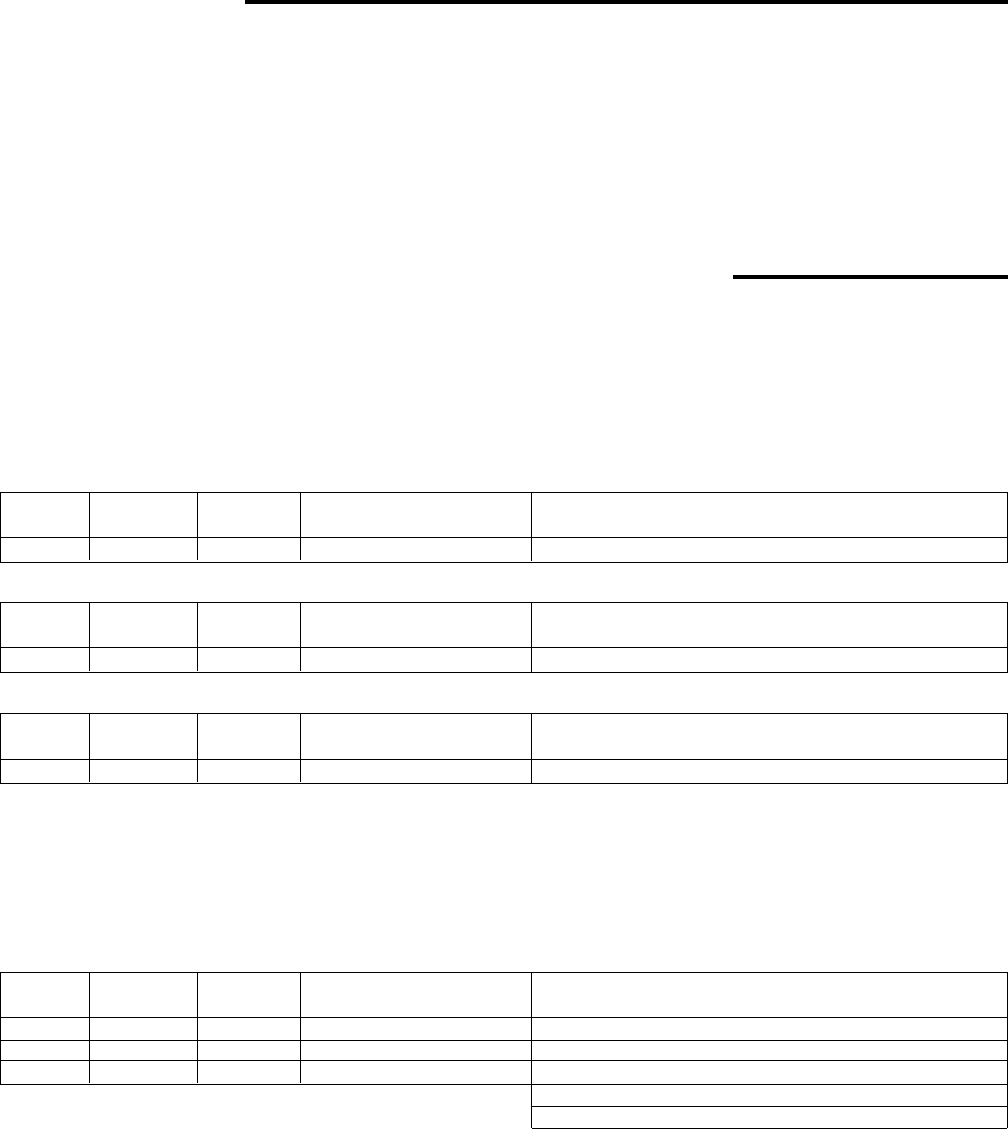
Tables 1-3 show how priority (LO, AVG, HI) effects the room temperature calculation. The example below table three shows
the calculation of each remote sensor and how it uses them to arrive at room temperature average.
Table 1: Remote Sensor A configured as a LO priority sensorTable 1: Remote Sensor A configured as a LO priority sensor
Table 1: Remote Sensor A configured as a LO priority sensorTable 1: Remote Sensor A configured as a LO priority sensor
Table 1: Remote Sensor A configured as a LO priority sensor
RemoteRemote
RemoteRemote
Remote
SensorSensor
SensorSensor
Sensor
PriorityPriority
PriorityPriority
Priority
SensorSensor
SensorSensor
Sensor
PriorityPriority
PriorityPriority
Priority
MultiplierMultiplier
MultiplierMultiplier
Multiplier
Room TemperatureRoom Temperature
Room TemperatureRoom Temperature
Room Temperature
Averaging CalculationAveraging Calculation
Averaging CalculationAveraging Calculation
Averaging Calculation
SA LO 1 70°F (Sensor Temp.) 1 x 70 = 70 (Priority Multiplier x Room Temp.)
Table 2: Remote Sensor B configured as a AVG priority sensorTable 2: Remote Sensor B configured as a AVG priority sensor
Table 2: Remote Sensor B configured as a AVG priority sensorTable 2: Remote Sensor B configured as a AVG priority sensor
Table 2: Remote Sensor B configured as a AVG priority sensor
RemoteRemote
RemoteRemote
Remote
SensorSensor
SensorSensor
Sensor
PriorityPriority
PriorityPriority
Priority
SensorSensor
SensorSensor
Sensor
PriorityPriority
PriorityPriority
Priority
MultiplierMultiplier
MultiplierMultiplier
Multiplier
Room TemperatureRoom Temperature
Room TemperatureRoom Temperature
Room Temperature
Averaging CalculationAveraging Calculation
Averaging CalculationAveraging Calculation
Averaging Calculation
SB AVERAGE 2 75°F (Sensor Temp.) 2 x 75 = 150 (Priority Multiplier x Room Temp.)
Table 3: Remote Sensor C configured as a HI priority sensorTable 3: Remote Sensor C configured as a HI priority sensor
Table 3: Remote Sensor C configured as a HI priority sensorTable 3: Remote Sensor C configured as a HI priority sensor
Table 3: Remote Sensor C configured as a HI priority sensor
RemoteRemote
RemoteRemote
Remote
SensorSensor
SensorSensor
Sensor
PriorityPriority
PriorityPriority
Priority
SensorSensor
SensorSensor
Sensor
PriorityPriority
PriorityPriority
Priority
MultiplierMultiplier
MultiplierMultiplier
Multiplier
Room TemperatureRoom Temperature
Room TemperatureRoom Temperature
Room Temperature
Averaging CalculationAveraging Calculation
Averaging CalculationAveraging Calculation
Averaging Calculation
SC HI 4 80°F (Sensor Temp.) 4 x 80 = 320 (Priority Multiplier x Room Temp.)
The example below lists three sensors each with a different priority and room temperature. All three sensors are combined in
the calculation to display the average temperature. The priority multiplier shown in the tables above causes a sensor with
low priority to carry less weight in the calculated average. A sensor with a HI priority setting contributes more to the calcu-
lated average. Assume that the building in which the thermostat is located has three indoor remote sensors (SA, SB, SC)
that have different room temperatures (70, 75, 80). The calculated average will be displayed as the room temperature
shown in the example below.
Example: Remote Sensors A, B, and C configured as a LO, AVG, and HI priority sensorsExample: Remote Sensors A, B, and C configured as a LO, AVG, and HI priority sensors
Example: Remote Sensors A, B, and C configured as a LO, AVG, and HI priority sensorsExample: Remote Sensors A, B, and C configured as a LO, AVG, and HI priority sensors
Example: Remote Sensors A, B, and C configured as a LO, AVG, and HI priority sensors
RemoteRemote
RemoteRemote
Remote
SensorSensor
SensorSensor
Sensor
PriorityPriority
PriorityPriority
Priority
SensorSensor
SensorSensor
Sensor
PriorityPriority
PriorityPriority
Priority
MultiplierMultiplier
MultiplierMultiplier
Multiplier
Room TemperatureRoom Temperature
Room TemperatureRoom Temperature
Room Temperature
Averaging CalculationAveraging Calculation
Averaging CalculationAveraging Calculation
Averaging Calculation
SA LO 1 70°F (Sensor Temp.) 1 x 70 = 70 (Priority Multiplier x Room Temp.)
SB AVERAGE 2 75°F (Sensor Temp.) 2 x 75 = 150 (Priority Multiplier x Room Temp.)
SC HI 4 80°F (Sensor Temp.) 4 x 80 = 320 (Priority Multiplier x Room Temp.)
Avg. Calc. (540)/Sum Priority Mult. (7)
540/7 = 77°F (Calculated Displayed Temp.)