


5
▲
! WARNING
Do not attempt repair of this unit unless you are
familiar with the necessary tools, equipment, utility
connections and potential hazards.
Repair should be performed only by a qualified
service provider.
Failure to do so could result in reduced performance
of the unit, serious personal injury or death.
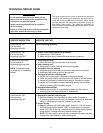
TECHNICAL REPAIR GUIDE
This guide contains service checks to assist service personnel
in locating and correcting any malfunction that might occur to
render the air cleaner ineffective or inoperative. The air cleaner
has been designed with replaceable components, such as the
high-voltage power supply. This allows the serviceman to
replace a faulty component rather than attempt repairs of such
components in the field.
SERVICE INDICATION SERVICE CHECKS
Control switch “ON” Unit functioning Normally.
Fan operating
Operating Light ON
Control switch “ON” 1. Power is not being supplied to air cleaner.
Fan not operating A. Check fuse or circuit breaker.
Operating Light OFF B. Make sure that door is closed and safety switch is pushed in.
Excessive arcing during 1. Collecting cell dirty.
normal operation – A. Clean cell thoroughly as instructed in this manual.
Operating Light may blink 2. Wet collecting cell.
A. Allow cell to dry after cleaning before applying power.
NOTE: Occasional arcing 3. Excessive airborne material.
or “snapping” is considered A. Additional air cleaner(s) may be required in extreme environments.
normal. B. Additional clean make-up air may be required.
4. Damaged or shorted collecting cell.
A. Inspect cell for bent plates. Straighten plates as necessary.
B. Check for foreign objects shorting across cell plates or ionizing section.
C. Inspect cell for loose or broken ionizing wire(s). Replace as needed.
D. Inspect cell for cracked or broken insulator(s), around cell perimeter.
Replace collecting cell if condition persists.
5. Damaged charcoal filter.
A. Remove charcoal filter. If arcing/snapping stops, the filter may be
breaking down and require disposal or replacement.
Control switch “ON” 1. Damaged or shorted collecting cell.
Fan operating A. Remove collecting cell. Close door so safety switch is pushed in.
Operating Light OFF If Operating light comes ON with cell removed, check cell as described
above. If light does not come ON, proceed to next step.
2. Power Supply.
A. Remove collecting cell. With safety switch pushed in, 120 VAC should
be present at terminals marked “LINE” on power supply. If voltage is
below 6100 VDC at red high voltage terminal on power supply, replace
power supply. If voltage is correct, replace indicator light.
NOTE: Unit may require up to one hour of operation to reach indicated
voltage when first installed or when replacing cell.