


8
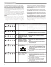
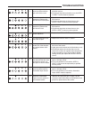
Error Indication Check, Repair, or Replace
A
B
C
1
An open earth ground cir-
cuit to the ignition system
1. Check that the earth ground conductor is properly
connected at the fuse box or breaker panel and the
water heater.
2. Check that the grounding conductors on the water
heater are properly connected and secure.
A
B
C
2
The self diagnostic test
detected a wiring error or
a high resistance to earth
ground
1. Check for proper connection of the line neutral and
line hot wires.
2. Check that the appliance is securely connected to
earth ground.
A
B
C
3
The pressure switch re-
mained closed longer that
5 seconds after the call for
heat began.
1. The pressure switch wiring is incorrect.
2. The pressure switch is defective and must be
replaced.
A
B
C
4
The pressure switch re-
mained open longer than 5
seconds after the combus-
tion blower was energized
1. The pressure switch wiring is incorrect.
2. The pressure switch tubing is not connected cor-
rectly.
3. Obstructions or restrictions in the water heater air
intake or exhaust flue.
A
B
C
5
The self diagnostic test has
detected an error in the Hot
Surface Ignitor circuit.
1. Check that all wiring is correct and secure.
2. Disconnect the ignitor and measure the ignitor re-
sistance with an accurate ohmmeter between pins
1 and 2. Resistance should be between 11.5 and
18.8 ohms. If the reading is incorrect, replace the
Hot Surface Ignitor.
3. If the above checks are good, replace the INTELLI-
VENT™ control.
A
B
C
6
The maximum number of
ignition retries or recycle
has been reached and the
system is in lockout
1. Check if the gas supply is off or too low to operate.
2. Check that the flame sense rod to see that it is
located properly and free from contamination.
Reposition the flame sense rod or lightly clean with
an abrasive cloth.
3. The Hot Surface Ignitor may not be positioned cor-
rectly. Reposition as necessary.
4. The Hot Surface Ignitor and Flame Sense Rod
wired correctly and in good working condition.
Repair as required.
5. Low voltage to the water heater. Check and repair.
The troubleshooting charts cover the error codes that the
Intelli-Vent™ control can recognize, the potential cause, and
those actions that may help repair the problem. The water
heater manufacturer’s troubleshooting procedure should be
consulted before attempting to repair the appliance. The wa-
ter heater manufacturer’s instructions take priority over the
instructions here.
If for any reason you question your ability, or feel any doubt
about your ability to perform any of the troubleshooting pro-
cedures or repairs recommended. STOP! Contact a trained
and qualified service professional to repair the water
heater.
To troubleshoot the system using the error code indicators:
1. Check that the system is currently active and calling for a
request for heat. You can initiate a call for heat by either
drawing hot water from a nearby faucet or raising the tem-
perature setting (see section “Temperature Regulation”).
If you have noted an error code from a previous heating
cycle, this step is not necessary, and you may proceed
with the next step.
2. Refer to the troubleshooting charts on below to find the
error code that is displayed. Check and repair those items
recommended.
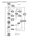
3. Once the repair is complete, again initiate a call for heat,
and observe that the ignition sequence complies with that
shown on page 7.
4. After the water heater repair is complete, return the water
heater temperature setting to the original temperature. If
for any reason you cannot remember the original setting,
return the setting to the 120
o
F setpoint. See the section
“Temperature Regulation” for assistance in setting the wa-
ter temperature setting.
TROUBLESHOOTING
2341