


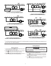
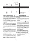

3
RH
24 VAC
120 VAC
Hot
Neutral
THERMOSTAT
SYSTEM
G W
Figure 2. Typical wiring diagram for
heat only, 3-wire, single transformer systems
TRANSFORMER
Heating
System
Fan
Relay
YC
‡
RC
JUMPER
WIRE
OB
For 2-wire Heat only,
attach to RH and W
NOTE
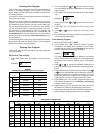
RH
Y
24 VAC
120 VAC
Hot
Neutral
TRANSFORMER
THERMOSTAT
SYSTEM
G W
Figure 3. Typical wiring diagram for
cool only, 3-wire, single transformer systems
Cooling
System
Fan
Relay
RCOB
C
‡
JUMPER
WIRE
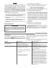
RH
Y
24 VAC
120 VAC
Hot
Neutral
THERMOSTAT
SYSTEM
G W
Figure 4. Typical wiring diagram for
heat/cool, 4-wire, single transformer systems
TRANSFORMER
Heating
System
Fan
Relay
Cooling
System
RC
JUMPER
WIRE
OC
‡
B
RED jumper wire (provided with thermostat) must be
connected between thermostat RH and RC terminals
for proper thermostat operation with this system.
NOTE
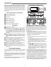
RH
Y
24 VAC
120 VAC
Hot
Neutral
THERMOSTAT
SYSTEM
G W
Figure 5. Typical wiring diagram for
heat/cool, 5-wire, two-transformer systems
HEATING
TRANSFORMER
Heating
System
Fan
Relay
Cooling
System
RC
24 VAC
120 VAC
Hot
Neutral
COOLING TRANSFORMER
OBC
‡
RH
Y
24 VAC
120 VAC
Hot
Neutral
THERMOSTAT
SYSTEM
G W
Figure 6. Typical wiring diagram for heat pump
with reversing valve energized in COOL
TRANSFORMER
Reversing
Valve*
RCOBC
‡
JUMPER
WIRE
Compressor
Contactor
JUMPER
WIRE
* Reversing valve is energized when the
system switch is in the COOL position
Fan
Relay
RH
Y
24 VAC
120 VAC
Hot
Neutral
THERMOSTAT
SYSTEM
G W
Figure 7. Typical wiring diagram for heat pump
with reversing valve energized in HEAT
TRANSFORMER
Reversing
Valve*
RCO
B
C
‡
JUMPER
WIRE
Compressor
Contactor
JUMPER
WIRE
* Reversing valve is energized when the
system switch is in the HEAT position
Fan
Relay
‡
The 24 Volt neutral connection to terminal C on the thermostat is not required if the batteries are replaced once a
year with fresh “AA” alkaline batteries.
Heating System
1. Move SYSTEM switch to HEAT position. If the heating system
has a standing pilot, be sure to light it.
2. Press
to adjust thermostat setting above room tempera-
ture. The heating system should begin to operate.
3. Press
to adjust thermostat setting below room tempera-
ture. The heating system should stop operating.
1. Move SYSTEM switch to COOL position.
2. Press
to adjust thermostat setting below room tempera-
ture. The blower should come on immediately on high speed,
followed by cold air circulation
3. Press
to adjust thermostat setting above room tempera-
ture. The cooling system should stop operating.
Cooling System
To prevent compressor and/or property damage, if the
outdoor temperature is below 50°F, DO NOT operate
the cooling system.
CAUTION
!