


3
WIRING CONT.
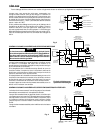
DIAGRAM FOR BOILER WITH TANKLESS DOMESTIC COIL
X X
T
1
4
2
3
T
5
6
X
X
TRANS.
HIGH LIMIT
24 VAC
GAS VALVE
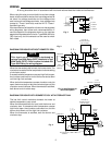
Fig. 5a & 6a Diagram for
Gas-Fired System
THERMOSTAT
TYPE 668 OIL
BURNER CONTROL
(LINE VOLTAGE)
HOT
LINE
N
TYPE 11B05
CIRCULATOR
CONTROL
BURNER
MOTOR
CIRCULATOR
MOTOR
IGNITION
TRANS.
HIGH
LIMIT
LOW
LIMIT
TYPE
11B30
THERMOSTAT
TYPE 668 OIL
BURNER CONTROL
(LINE VOLTAGE)
FIELD
INSTALLED
JUMPERS
BURNER
MOTOR
CIRCULATOR
MOTOR
HOT
LINE
N
IGNITION
TRANS.
CIRCULATOR
CONTROL
HIGH
CONTROL
LOW
LIMIT
Fig. 5 Diagram for System using High Limit-Low Limit
control and Circulator control.
Fig. 6 Diagram for System using High Limit control and
Low Limit-Circulator control.
The low limit control maintains domestic hot water at
desired temperature year-round.
When the thermostat calls for heat, the burner starts. The
circulator also starts if boiler temperature is above setting
of circulator control.
If excessive boiler temperature causes high limit to open,
the circulator continues to run but the burner shuts down
until the high limit recloses.
When low boiler temperature causes the circulator control
to open, burner stays on but the circulator stops until the
circulator control recloses. When thermostat is satisfied,
the circulator stops. The burner also shuts down if boiler
temperature is above setting of low limit control.
T
1
4
2
3
T
5
6
ZC
ZR
B1
B2
C1
C2
1
2
T
T
THERMOSTAT
ZONE 2
THERMOSTAT
ZONE 1
TO CIRCULATOR
ZONE 1
HOT
LINE
N
TO BURNER
TO ADDITIONAL 829A-845 RELAYS
FOR OTHER ZONES
*CIRCULATOR
ZONE 2
JUMPER
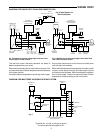
*Terminal No. 4 or No. 6 may go to zone 2,
The other terminal then goes to ZR.
DIAGRAM FOR MULTIZONE HYDRONIC HEATING SYSTEM
Fig. 7
FIELD
INSTALLED
JUMPERS
X X
T
1
4
2
3
T
5
6