


WHITE-RODGERS
TT
1
2
3
4
5
6
Printed in U.S.A.
PART NO. 37-2689D
Replaces 37-2689-3
9512
TYPE 829A-845
RELAY
For Use With Low Voltage Thermostats
INSTALLATION INSTRUCTIONS
Operator: Save these instructions for future use!
WHITE-RODGERS DIVISION
EMERSON ELECTRIC CO.
9797 REAVIS RD., ST. LOUIS, MO. 63123
(314) 577-1300, FAX (314) 577-1517
9999 HWY. 48, MARKHAM, ONT. L3P 3J3
(905) 475-4653, FAX (905) 475-4625
R
DESCRIPTION
FAILURE TO READ AND FOLLOW ALL INSTRUCTIONS CAREFULLY BEFORE
INSTALLING OR OPERATING THIS CONTROL COULD CAUSE PERSONAL
INJURY AND/OR PROPERTY DAMAGE.
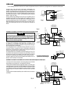
Type 829A-845 Relay has double-pole, single-throw
switching action.
This relay is especially suitable for use on hot water
heating installations having forced circulation. It permits
the use of a sensitive low voltage room thermostat to
control the operation of both burner and circulator.
It is equally well suited for use on zoned hot water
installations where a circulator and low voltage thermostat
are used for each zone.
ELECTRICAL DATA
Switch Action: Double-Pole, Single-Throw, normally open
Input Voltage: Terminals (1 & 2) 120V.A.C., 60Hz
Room Thermostat:
Set adjustable heat anticipator at 0.3 Amps. For fixed
anticipation thermostats, use 0.25 to 0.35 Amp. heater.
Rating: Terminals (3 & 4 and 5 & 6)
Total load must not exceed 2000 VA.
Motor: 120V.A.C. 10F.L.A. 60L.R.A.
240V.A.C. 6F.L.A. 36L.R.A.
Pilot Duty:50VA @ 24 Volts
SPECIFICATIONS
To prevent electrical shock and/or equipment
damage, disconnect electric power to system, at
main fuse or circuit breaker box, until installation
is complete.
If in doubt about whether your wiring is millivolt, line, or
low voltage, have it inspected by a qualified heating and
air conditioning contractor, electrician, or someone famil-
iar with basic electricity and wiring.
Do not exceed the specification ratings.
All wiring must conform to local and national electrical
codes and ordinances.
This control is a precision instrument, and should be
handled carefully. Rough handling or distorting compo-
nents could cause the control to malfunction.
PRECAUTIONS
CAUTION
Do not use on circuits exceeding specified
voltages. Higher voltages will damage control
and could cause shock or fire hazard.
WARNING
PRINCIPLE OF OPERATION
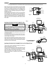
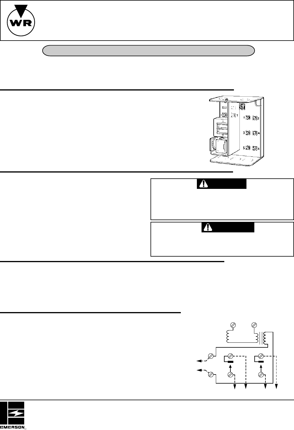
The 829A-845 relay is provided with a self-contained
transformer with a low voltage secondary output for
energizing the relay coil.
Line voltage lines should be connected to the terminals
marked “1 & 2” for power to reach the transformer.
Closing the thermostat circuit energizes the relay coil which
in turn closes the circuits between terminals 3 and 4 and also
between 5 and 6.
Opening the thermostat circuit de-energizes the relay coil,
breaking the circuits between terminals 3 and 4 and also
between 5 and 6.
DOTTED LINES
INDICATE FIELD
WIRING
Fig. 1
RELAY
COIL
N
LINE
HOT
TO LINE AND LOAD
OR PILOT DUTY
TO LINE AND LOAD
OR PILOT DUTY