SETTING THE DIAL
Wiring
All wiring must conform to local and national electrical codes and ordinances.
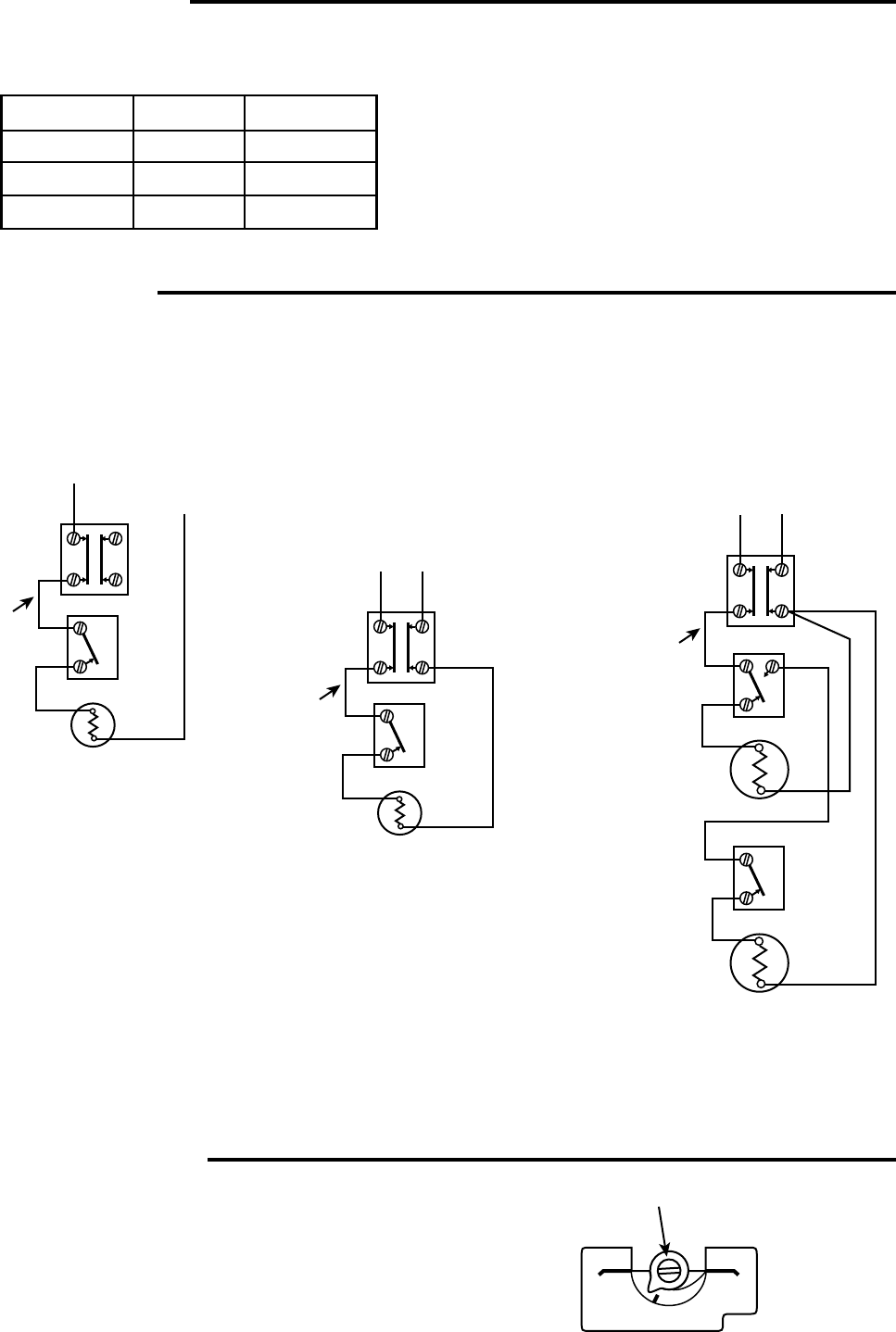
Connect in accordance with wiring diagrams provided by the equipment manufacturer. If none are provided,
the following represents a typical installation.
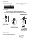
Adjust temperature setting by inserting a screwdriver into
open slot and turning pointer to desired temperature on
dial.
Adjustment Slot
150°F
66°C
125°F/52°C
90°F
32°C
INSTALLATION
Heating Element
L1
L2
1
2
1
2
3
4
Field
Installed
Jumper
754-1
755-1
240 VAC SIngle Element Circuit
for Full Power Disconnect
Through Both Power Conductors
Heating Element
L1
N
1
2
1
2
3
4
Field
Installed
Jumper
754-1
755-1
Upper Heating
Element
L1
L2
1
2
1
2
3
4
4
Lower
Heating Element
1
2
Field
Installed
Jumper
756-1
755-1
754-1
120 VAC Single Element
Circuit for Full Power
Disconnect
240 VAC Double Element
Limited Demand Circuit for
Full Power Disconnect
Through Both Power Con-
ductors
Two-Element
Non-Simultaneous Operation
SPECIFICATIONS
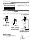
AC ELECTRICAL RATINGS:
UL and CSA recognized for resistive loads.
Temperature Ratings:
Temperature control - Variable 90° to 150°F (32° to
66°C)
Limit control - Fixed 170°F (77°C) with manual reset
Temp Control Voltage Limit Control
30 Amps 120-250 VAC 40 Amps
25 Amps 277 VAC 40 Amps
12.5 Amps 480 VAC 25 Amps


