


2
INSTALLATION (CONT.)
The elements should be bent so that they will not touch the
heated surface or be affected by reflected or radiated heat
unless such a position is determined by the furnace manu-
facturer.
Care must be used when bending the element to prevent
“kinking” it. The element should not be bent with a radius of less
than one inch and all bending should be done between the coiled
part of the element and a point one inch from the diaphragm cup.
The element should be shaped over the thumbs so that a round
bend is obtained.
On remote controls, the long capillary tubing between the
sensitive bulb and the switch mechanism should be led over a
path that will protect it from cuts, blows, wear due to vibration,
etc.
Use the paper template packed with the control to obtain the
mounting dimensions.
CAUTION
The limit control is a safety device. The manufacturer of
the furnace as well as testing agencies (U.L., AGA, CGA)
have made many tests on the furnace to determine the
proper dial setting.
The limit dial should never be set any higher than the
setting it had when the furnace was delivered. Do not
force the dial past any stop on the dial even though the
dial may be graduated beyond the stop.
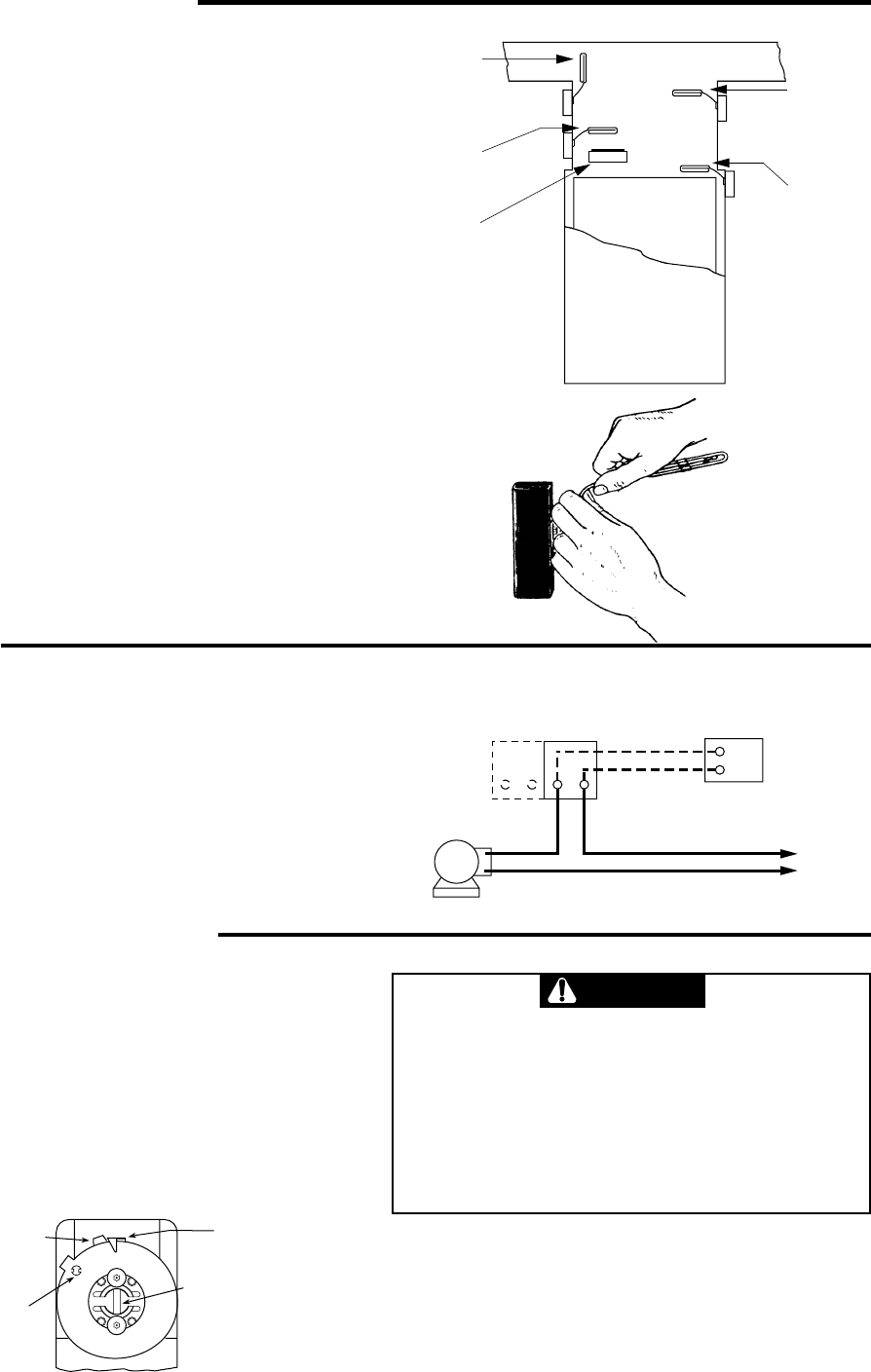
1. Loosen stop screw (E) with enclosed wrench.
2. Set dial to original equipment manufacturer’s specification.
3. Without moving the dial, move stop tab (F) against indicator.
4. Retighten stop screw (E).
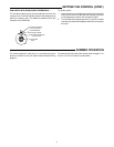
SETTING THE CONTROL
LIMIT SWITCH WITH A FIXED DIFFERENTIAL
The indicator (B) points to the temperature at which the contacts
open.
To set the control:
Use a screwdriver in the adjusting slot (A) on the front of the
control to rotate dial until the desired temperature at which
the contacts will open is positioned directly under the
indicator (B).
“B” FIXED
INDICATOR
“A” ADJUSTING
SLOT
“E” STOP SCREW
“F” STOP TAB
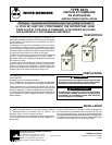
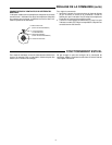
If the furnace or burner manufacturer recommends a wiring
diagram, then follow such recommendations. If none are of-
fered, connect the fan side (right hand switch) as shown in the
diagram on this page.
Connect the limit side (left hand switch) according to wiring
diagrams packed with the primary control, gas valve, oil burner
control or stoker control.
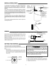
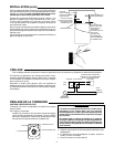
ELEMENT
AFFECTED
BY AIR GOING
TO ONLY ONE DUCT
AIR FLOW OVER
ELEMENT AFFECTED
BU HUMIDIFIER
HUMIDIFIER
NORMALLY
GOOD ELEMENT
LOCATION
ELEMENT MAY BE
TOO CLOSE TO
SOURCE OF HEAT
UNLESS SUCH
POSITION IS
DETERMINED BY
FURNACE
MANUFACTURER
LIMIT FAN
REMOTE MANUAL SWITCH
FOR SUMMER FAN OPERATION
(IF USED)
FAN
MOTOR
TYPE
5A75
HOT
LINE
N
WIRING
All wiring should be done in accordance with local and national electrical codes and ordinances.