


Location
Mount the relay on a fl at, solid surface inside the equipment
control box. The relay may be panel- or wall-mounted with
the base vertical or horizontal. If base is horizontal, it must be
mounted with the terminals up. Secure with the two screws
through holes or slots in the mounting base or as shown in
Fig. 1.
Wiring
Disconnect power supply before connecting wiring to prevent
electrical shock or equipment damage.
All wiring must comply with local codes and ordinances.
Crimp female quick-connects to the system wires, if needed,
and attach to the male quick-connect terminals on the time
delay board.
Terminal designations on 57T01-843 correspond directly to
terminal designations on RLY02807 and RLY02257 relay.
Therefore, wires are to be connected to the same lettered or
numbered terminal on the 57T01-843 relay as they were on
the RLY02807 and RLY02257 relay. For example, the wire
connected to terminal #4 on RLY02807 or RLY02257 relay
should be connected to terminal #4 on 57T01-843 relay, etc.
Terminals 1 (COM) and 3 (N.O.) are high voltage fan relay
terminals.
No Off Delay Wiring
For No Off delay operation remove the red wire from terminal
“A” and the green wire from terminal “T.” Take the red wire that
was removed from terminal “A” and connect to terminal “T.”
Next take the green wire that was removed from terminal “T”
and connect to terminal “A.” You may hear a double click when
energized which is normal.
Make sure all wires are connected to the proper terminals on
the time delay board for proper system operation. Refer to
Figs. 1-4 for terminal designations and wiring connections.
Do not exceed contact and coil ratings when wiring into
system.
1 (COM)
3 (NO)
Refer to label on side
of relay for information
on terminal functions.
AB 6T 4
K2
K1
R1
R2
R8
R12
E4
RV1
C6
C7
C5
C3
C1
E1
E2
E3
E5
A
B
1 (COM)
HIGH VOLTAGE FAN
3 (NO)
6
T
4
24 VAC Rd
from Transformer
24 VAC Common BL
from Transformer
WH/J to Heater Plug
Connection
GR from LV Field
Connection
BL Common from
LV Field Connection
B
T
A63
4 1
Operation
When the thermostat calls for indoor blower operation, an
electronic switch in the electronic board pulls in and powers
the relay coil. When the call ends, the electronic switch in the
electronic board holds in the relay coil for an additional 80
seconds. This increases the effi ciency of the equipment and
saves energy.
NOTE: When power is initially applied during installation or
after power interruption, the relay will pull in for a maximum of
0.5 seconds and then drop out.
Checkout
When power is initially applied, check to make sure the relay
pulls in for not more than 0.5 seconds and drops out. Then
operate the relay and controlled equipment to make sure
that the relay pulls in when the T terminal is energized with
24 VAC and that controlled equipment operates as intended.
Relay pulls in after a short on delay of 2 seconds (±0.7).
When the T terminal is deenergized (24 VAC removed), the
indoor air blower should continue to operate until the delay
period (80 seconds) ends.
OPERATION AND CHECKOUT
www.white-rodgers.com
St. Louis, Missouri
White-Rodgers is a division
of Emerson Electric Co.
The Emerson logo is a
trademark and service mark
of Emerson Electric Co.
INSTALLATION
BT
TIME DELAY BOARD
46
13
5
A
2
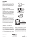
TERMINAL
DESIGNATION
CONNECTION
A 24 Vac LINE (HOT SIDE)
24 Vac COMMON
FAN TERMINAL ON THERMOSTAT
OR OTHER CONTROLLER
B
T
Fig. 1. Mounting 57T01-843 on panel
Fig. 2. 57T01-843 Terminal Designations
Fig. 3. Mounting 57T01-843 on panel
Fig. 4. 57T01-843 Circuit and terminal designations