


6
OPERATION
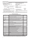
OPTION SWITCHES
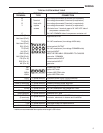
The option switches on the 50A66-743 control are used
to determine the length of the heat delay-to-fan-off period.
The following table shows the time periods that will result
from the various switch positions.
HEAT delay-
to-fan-off:
Set switch
#1 #2
60 sec.
90 sec.*
120 sec.
180 sec.
Off Off
Off On
On Off
On On
COOL delay-
to-fan-off:
Set switch
#3
2 sec.
45 sec.*
Off
On
OPTION SWITCH POSITIONS
* Factory Setting
HEAT MODE
In a typical system, a call for heat is initiated by closing
the thermostat contacts. This starts the 50A66 control’s
heating sequence. The inducer blower and humidifier are
energized. After a 15-second prepurge period, the 768A
Silicon Nitride ignitor is powered.
This controller has an adaptive algorithm that reduces the
ignitor temperature to slightly greater than the minimum
temperature required to ignite gas in each particular
application. The control measures the line voltage and
determines an initial ignitor temperature setting based
on the measurement. After each successful ignition, the
control lowers the ignitor temperature slightly for the next
ignition attempt. The control continues to lower the ignitor
temperature until ignition does not occur, and the control
goes into retry mode. For the second attempt to ignite
gas within the same call for heat, the control increases
the ignitor temperature to the value it was on the third
previous successful ignition. After ignition is successful,
the control sets the ignition temperature at this value for
the next 255 calls for heat, after which the control repeats
the adaptive algorithm. The control is constantly making
adjustments to the ignitor temperature to compensate for
changes in the line voltage.
The 80 VAC Silicon Nitride ignitor manufactured by
White-Rodgers must be used. These ignitors are special-
ly designed to operate with the 50A66’s adaptive ignition
routine to ensure the most efficient ignitor temperature.
At the end of the ignitor warm-up time, both valves in
the 36E manifold gas valve are opened. Flame must be
detected within 4 seconds.
If flame is detected, the delay-to-fan-on period begins.
After the delay-to-fan-on period ends, the circulator fan is
energized at heat speed. If there is an optional electronic
air cleaner on the system, the electronic air cleaner and
the humidifier are energized. When the thermostat is
satisfied, the gas valve is de-energized. After proof of
flame loss, the inducer blower remains energized to purge
the system for 5 seconds and the delay-to-fan-off period
begins. When the purge is complete, the inducer blower
and humidifier are de-energized. After the delay-to-fan-off
period ends, the circulator fan and electronic air cleaner
are de-energized.
If flame is not detected, both valves are de-energized,
the ignitor is turned off, and the 50A66 control goes into
the “retry” sequence. The “retry” sequence provides a
15-second wait following an unsuccessful ignition attempt
(flame not detected). After this wait, the ignition sequence
is restarted. If this ignition attempt is unsuccessful, three
more retries will be made before the control goes into
system lockout.
If flame is detected, then lost, the 50A66 control will repeat
the initial ignition sequence for a total of three “recycles”.
After three unsuccessful “recycle” attempts, the control
will go into system lockout.
If flame is established for more than 10 seconds after
ignition, the 50A66 controller will clear the ignition attempt
(or retry) counter. If flame is lost after 10 seconds, it will
restart the ignition sequence. This can occur a maximum
of four times before system lockout.
A momentary loss of gas supply, flame blowout, or a
shorted or open condition in the flame probe circuit will be
sensed within 2 seconds. The gas valve will de-energize
and the control will restart the ignition sequence. Recycles
will begin and the burner will operate normally if the gas
supply returns, or the fault condition is corrected, before
the last ignition attempt. Otherwise, the control will go
into system lockout.
If the control has gone into system lockout, it may be possi-
ble to reset the control by a momentary power interruption
of ten seconds or longer. Refer to PRECAUTIONARY,
SYSTEM LOCKOUT, AND DIAGNOSTIC FEATURES.
COOL MODE
In a typical system, a call for cool is initiated by closing
the thermostat contacts. This starts the 50A66 control’s
cooling sequence. The compressor is energized and the
delay-to-fan-on period begins. After the delay-to-fan-on
period ends, the circulator fan is energized at cool speed.
The electronic air cleaner (optional) is also energized. After
the thermostat is satisfied, the compressor is de-energized
and the delay-to-fan-off period begins. After the delay-to-
fan-off period ends, the circulator fan and electronic air
cleaner are de-energized.
MANUAL FAN ON MODE
If the thermostat fan switch is moved to the ON position,
the circulator fan (heat speed) and optional electronic air
cleaner are energized. When the fan switch is returned
to the AUTO position, the circulator fan and electronic air
cleaner (optional) are de-energized.