


2
SPECIFICATIONS
INSTALLATION
ELECTRICAL RATINGS [@ 77°F (25°C)]:
Input Voltage: 25 VAC 50/60 Hz
Max.InputCurrent@25VAC:0.45 amp
Relay Load Ratings:
Valve Relay: 1.5 amp @ 25 VAC 50/60 Hz 0.6 pf
Ignitor Relay: 6.0 amp @ 120 VAC 50/60 Hz
(resistive)
Inducer Relay: 2.2 FLA–3.5 LRA @ 120 VAC
Circulator Relay: 14.5 FLA–25.0 LRA @ 120 VAC
Flame Current Requirements:
Minimum current to insure flame detection: 1 µa DC*
Maximum current for non-detection: 0.1 µa DC*
Maximum allowable leakage resistance: 100 M ohms
*Measured with a DC microammeter in the flame probe lead
OPERATING TEMPERATURE RANGE:
-40° to 175°F (-40° to 80°C)
HUMIDITY RANGE:
5% to 93% relative humidity (non-condensing)
MOUNTING:
Surface mount multipoise
Timing Specs: (@ 60 Hz**)
maximum
Flame Establishing Time: 0.8 sec
Flame Failure Response Time: 2.0 sec
**At 50 Hz, all timing specifications should be increased
by 20%
GasesApproved:Natural, Manufactured, Mixed, Liqui-
fied Petroleum, and LP Gas Air Mixtures are all approved
for use.
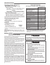
50A55-743
Pre-Purge 15
Initial Ignitor Warm-up
(1
st
64 attempts)
7
Minimum Ignitor Warm-up 5
Maximum Ignitor Warm-up 9
Ignition Activation Period 2
Trial for Ignition Period 4
Retries 2 times
Valve Sequence Period 12
Interpurge 30
Post-Purge 15
Lockout Time 300
Heat Delay-To-Fan-On 30
Heat Delay-To-Fan-Off* 90/120/150/180
Cool Delay-To-Fan-On 5
Cool Delay-To-Fan-Off 45
Auto Reset 60 minutes
Humidifier Ye s
Electronic Air Cleaner Ye s
*These times will vary depending on option switch
position. See OPERATION section for further
information
TIMING SPECIFICATIONS
(All times are in seconds, unless noted otherwise
MOUNTING AND WIRING
All wiring should be installed according to local and na-
tional electrical codes and ordinances.
The control must be secured to an area that will experience
a minimum of vibration and remain below the maximum
ambient temperature rating of 175°F. The control is ap-
proved for minimum ambient temperatures of -40°F.
Any orientation is acceptable.
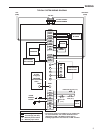
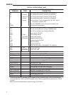
Refer to the wiring diagram and wiring table when connect-
ing the 50A55 control to other components of the system.
UL approved, 105°C rated 18 gauge, stranded,
2/64”
thick
insulation wire is recommended for all low voltage safety
circuit connections. Refer to 50A55 specification sheet for
recommended terminals to mate with those on the control.
UL approved 105°C rated 16 gauge min., stranded,
4/64”
thick insulation wire is recommended for all line voltage
connections. Refer to 50A55 specification sheet for rec-
ommended terminals to mate with those on the control.
After installation or replacement, follow appliance manu-
facturer’s recommended installation or service instructions
to ensure proper operation.
The 50A55 has only one serviceable part–an automotive
type fuse, which protects the low voltage transformer
from damage if its output is short-circuited. If the fuse
has opened up, remove whatever caused the short circuit
and replace the fuse with only a 3 Amp automotive type
fuse. If the fuse is not the cause of the control’s problem,
replace the entire 50A55 control. There are no other user
serviceable parts.
WARNING
!
FIRE HAZARD
• Donotexceedthespeciedvoltage.
• Replace existing control with exact model and
dash number.
• Protectthecontrolfromdirectcontactwithwater
(dripping, spraying, rain, etc.).
• Ifthecontrolhasbeenindirectcontactwithwater,
replace the control.
• Labelallwiresbeforedisconnectionwhenservic-
ing controls. Wiring errors can cause improper and
dangerous operation.
• Routeandsecurewiringawayfromame.
SHOCK HAZARD
• Disconnectelectricpowerbeforeservicing.
• Ensureproperearthgroundingofappliance.
• Ensureproperconnectionoflineneutralandline
hot wires.
EXPLOSION HAZARD
• Shutoffmaingastoapplianceuntilinstallationis
complete.
CAUTION
!
Donotshortoutterminalsongasvalveorprimary
control. Short or incorrect wiring may damage
the thermostat.