


7
gize and the control will restart the ignition sequence. A
recycle will begin and the burner will operate normally if
the gas supply returns, or the fault condition is corrected,
before the last ignition attempt. Otherwise, the control will
go into system lockout.
If the control has gone into system lockout, it may be
possible to reset the control by a momentary power
interruption of one second or longer. Refer to SYSTEM
LOCKOUT FEATURES.
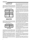
COOL MODE
In a typical system, a call for cool is initiated by closing the
thermostat contacts. This energizes the 50A55 control.
The compressor and optional electronic air cleaner are
energized, and the circulator fan is energized at cool
speed. After the thermostat is satisfied, the compressor is
de-energized and the (optional) cool mode delay-to-fan-
off period begins. After the optional delay-to-fan-off period
ends, the circulator fan and electronic air cleaner (op-
tional) are de-energized.
MANUAL FAN ON MODE
If the thermostat fan switch is moved to the ON position,
the circulator fan (heat speed) and optional electronic air
cleaner are energized. When the fan switch is returned to
the AUTO position, the circulator fan and electronic air
cleaner (optional) are de-energized.
SYSTEM LOCKOUT AND
DIAGNOSTIC FEATURES
SYSTEM LOCKOUT FEATURES
When system lockout occurs, the gas valve is de-ener-
gized, the circulator blower is energized at heat speed,
and, if flame is sensed, the inducer blower is energized.
The diagnostic indicator light will flash or glow continu-
ously to indicate system status. (System lockout will
never override any precautionary features.)
To reset the control after system lockout, do one of the
following:
1. Interrupt the call for heat or cool at the thermostat for
at least one second but less than 20 seconds (if flame
is sensed with the gas valve de-energized, interrupt-
ing the call for heat at the thermostat will not reset the
control).
2. Interrupt the 24 VAC power at the control for at least
one second. You may also need to reset the flame
rollout sensor switch.
3. After one hour in lockout, the control will automatically
reset itself.
DIAGNOSTIC FEATURES
The 50A55 control continuously monitors its own opera-
tion and the operation of the system. The LED light on the
control will flash slowly (one flash per second) if there are
no failures and no call for heat. If there is a call for heat,
the LED will flash quickly (one flash per half-second). If a
failure occurs, the LED will indicate a failure code as
shown below. If the failure is internal to the control, the
light will stay on continuously. In this case, the entire
control should be replaced, as the control is not field-
repairable. If the LED is continuously off, there may be no
power to the control; the fuse on the control may be open;
or there may be a failure in the control.
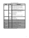
If the sensed failure is in the system (external to the
control), the LED will flash in the following flash-pause
sequences to indicate failure status (each flash will last
approximately 0.25 seconds, and each pause will last
approximately 2 seconds).
2 flashes, then pause System lockout (no flame)/check
line polarity
3 flashes, then pause Pressure switch problem
4 flashes, then pause Thermal protection device open
5 flashes, then pause Flame sensed with gas valve off
6 flashes, then pause 115 Volt AC power reversed
7 flashes, then pause Gas valve circuit error
8 flashes, then pause Low flame sense signal
The LED will also flash once at power-up.