


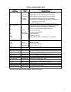
3
INSTALLATION
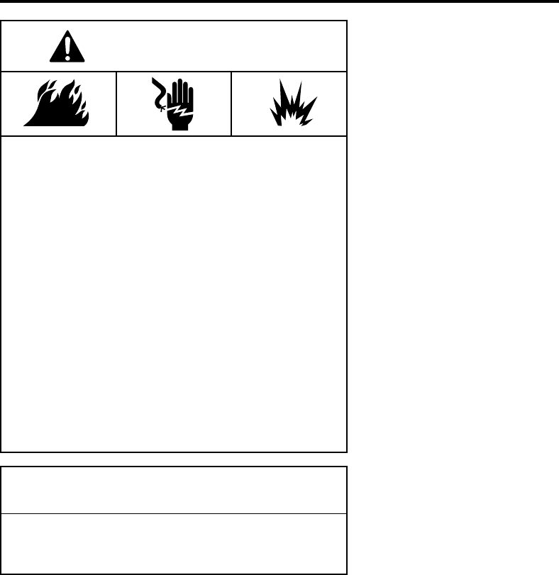
WARNING
CAUTION
FIRE HAZARD
• Do not exceed the specified voltage.
• Replace existing control with exact model and
dash number.
• Protect the control from direct contact with water
(dripping, spraying, rain, etc.).
• Label all wires before disconnection when servic-
ing controls. Wiring errors can cause improper
and dangerous operation.
• Route and secure wiring away from flame.
SHOCK HAZARD
• Disconnect electric power before servicing.
• Ensure proper earth grounding of appliance.
• Ensure proper connection of line neutral and line
hot wires.
EXPLOSION HAZARD
• Shut off main gas to appliance until installation is
complete.
Do not short out terminals on gas valve or primary
control. Short or incorrect wiring may damage the
thermostat.
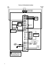
MOUNTING AND WIRING
All wiring should be installed according to local and national
electrical codes and ordinances.
The control must be secured to an area that will experience a
minimum of vibration and remain below the maximum ambient
temperature rating of 175°F. The control is approved for mini-
mum ambient temperatures of -40°F.
When mounting the control, any orientation is acceptable.
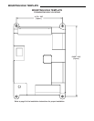
Choose a location that will not damage, obstruct or place stress
on the control’s terminations, system wiring harness or system
components. After finding a suitable location, drill four (4)
1
⁄8”
holes for mounting control. To ensure proper mounting hole
locations, there is a mounting hole template on page 8 of this
instruction sheet. Detach the page with the template from the
instruction sheet and apply it to the mounting location. When
drilling the holes, take care so that the transformer, wiring
harness or other system components are not damaged. Four (4)
#8 sheet metal screws are provided to complete the installation.
Refer to the wiring diagram and wiring table when connecting
the 50A55 control to other components of the system.
UL approved, 105°C rated 18 gauge, stranded,
2
⁄64” thick insula-
tion wire is recommended for all low voltage safety circuit
connections. Refer to 50A55 specification sheet for recom-
mended terminals to mate with those on the control.
UL approved, 105°C rated 16 gauge min., stranded,
4
⁄64” thick
insulation wire is recommended for all line voltage connections.
Refer to 50A55 specification sheet for recommended terminals
to mate with those on the control.
The 50A55 has only one serviceable part–an automotive type
fuse, which protects the low voltage transformer from damage
if its output is short-circuited. If the fuse has opened up, remove
whatever caused the short circuit and replace the fuse with only
a 3 Amp automotive type fuse. If the fuse is not the cause of the
control’s problem, replace the entire 50A55 control. There are
no other user serviceable parts.