


2
INSTALLATION
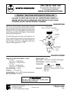
These gas valves should be installed according to the
following instructions. Check for gas leaks with a soap
solution after completing installation.
Never use flame to detect leaks.
Do not leave unused inlet unplugged.
DO NOT USE THESE GAS VALVES WITH
UNVENTED APPLICATIONS.
MAIN PIPING CONNECTIONS
1. Be sure the main gas supply is shut off before starting
the installation. The gas valve may be installed in any
position, but it should be located so that the gas
control knob is easily accessible.
2. Direction of gas flow is indicated by the directional
arrow on the outlet boss.
3. You should use new pipe, which has been properly
chamfered and reamed. If you use old pipe, be sure
it is clean and free of rust, scale, burrs, chips and old
pipe joint compound.
4. If the side inlet is to be used, it is necessary to remove
the plug and install it in the bottom inlet. This proce-
dure requires a
5
⁄16” Allen wrench. Be sure the end of
the plug is free of burrs, chips, etc. Before installing
plug, apply pipe joint compound (pipe dope) that is
approved for all gases, only to the male threads of the
plug. DO NOT apply compound to first two threads.
Do not overtighten the plug.
5. Apply pipe joint compound (pipe dope) that is ap-
proved for all gases, only to the male threads of pipe
joints. DO NOT apply compound to first two threads.
Do not thread pipe too far.
Applying pipe joint compound to pipe threads will prevent
chips from passing onto internal valve parts, since the
pipe joint compound will collect and retain chips that are
formed as the pipe is threaded into the body.
6. If a vise or open-end wrench is used to hold the control
while installing piping, do not tighten excessively, as
this may damage the control.
PILOT GAS CONNECTION
Install the fitting into the pilot gas tapping, turning until
finger-tight. Insert clean, deburred tubing all the way
through the fitting. Holding the tubing securely, slowly
tighten the fitting until a slight “give” is felt. Then tighten an
additional 1
1
⁄2 turns.
THERMOCOUPLE
The thermocouple connector should be clean for good
electrical contact. Run the thermocouple nut into the
thermocouple connection as far as possible by hand.
Then set the nut with
1
⁄4 to
1
⁄2 additional turn using a small
wrench. Do not overtighten.
NOTE
CAUTION
!
CAUTION
!
CAUTION
!