


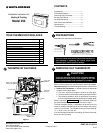

Model 350 (Heating and Cooling):
A. Remove base from subbase: Loosen the three screws on
the base and remove.
B. Mount switching subbase: Use the screws provided to mount
the subbase to wall (see Fig. 1).
C. Attach wires to appropriate terminals:
• For two wire systems (Heat Only or Cool Only). If you
have a two-wire Heat Only system, attach one wire to RH and
one to wire W. If you have a two-wire Cool Only system, attach
one wire to RC and one to wire to Y. Leave the factory
installed jumper between RC and RH attached. Tighten any
unused terminals securely.
• If your system has more than two wires: Use the cross
reference chart to determine correct wire connections. If you
have a four-wire heat/cool system leave the factory installed
jumper between RC and RH attached (see Fig 2.). If your
system has five wires remove the factory installed jumper
between RC and RH (see Fig 3.).
• Electric heat or single stage heat pump systems: This
thermostat is configured from the factory to operate a heat/
cool, fossil fuel (gas, oil, etc.) forced air system. It is configured
correctly for any system that DOES NOT require the thermo-
stat to energize the fan on a call for heat. If your system is an
electric heat or heat-pump system that REQUIRES the ther-
mostat to turn on the fan on a call for heat, remove the yellow
factory-installed jumper wire from the Y terminal and connect
MOUNTING AND WIRING
Take care when securing and routing wires so they do
not short to adjacent terminals or rear of thermostat.
Personal injury and/or property damage may occur.
CAUTION
!
ATTENTION! This product contains mercury. There will not be
any exposure to mercury under normal conditions of use. This
product may replace a unit which contains mercury.
Do not open mercury cells. If a cell becomes damaged, do not
touch any spilled mercury. Wearing non-absorbent gloves, take
up the spilled mercury and place into a container which can be
sealed. If a cell becomes damaged, the unit should be disgarded.
Mercury must not be discarded in household trash. When the unit
this product is replacing is to be discarded, place in a suitable
container and return to White-Rodgers at 9797 Reavis Road, St.
Louis, MO, 63123-5398 for proper disposal.
REMOVING OLD THERMOSTAT
CONTINUED FROM FIRST PAGE
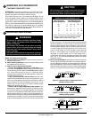
WARNING
!
Do not use on circuits exceeding specified voltage.
Higher voltage will damage control and could cause
shock or fire hazard.
Do not short out terminals on gas valve or primary
control to test. Short or incorrect wiring will damage
thermostat and could cause personal injury and/or
property damage.
Thermostat installation and all components of the sys-
tem shall conform to Class II circuits per the NEC code.
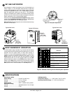
TERMINAL CROSS REFERENCE CHART
New Thermostat
Terminal Designation
Other Manufacturers’
Terminal Designation
RH
RC
G
W
Y
4
R
G
W
Y
RH
R
G
W
Y
M
V
F
H
C
R5
-
G
4
Y6
R
-
G
W
Y
**
* These are four-wire, single-transformer systems.
Factory installed jumper wire between the RH
and RC terminals must remain in place.
it to the A terminal. This will allow the thermostat to energize
the fan immediately on a call for heat. If you are unsure if the
heating system requires the thermostat to control the fan,
contact a qualified heating and air conditioning service person.
For single stage heat pump applications (no auxillary heat),
install a short jumper wire (not included) across terminals
W and Y. If the system has a reversing valve connection
energized in Cooling, attach it to O. If the system has a
reversing valve connection energized in Heating, attach it to B
(see Fig. 4). This thermostat will not provide multi-stage
heating or cooling.
D. Mount Thermostat Base: Gently push excess wire back into
the wall opening and plug hole with a fire-resistant material,
such as fiberglass insulation to prevent drafts from affecting
thermostat operation. Mount the thermostat base to the sub-
base using the three captive screws on the thermostat base.
(see Fig. 1) Tighten the screws securely. Proceed to Step #5.
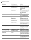
RH W B O Y G RC A
24 VAC
120 VAC
Hot
Neutral
TRANSFORMER
Heat
Relay
Compressor
Relay
Fan
Relay
Factory-Installed Jumper
Figure 2. Typical wiring for single transformer
heating/cooling system
Figure 3. Typical wiring for two-transformer
heating/cooling system
RH W B O Y GA
24 VAC
120 VAC
Hot
Neutral
TRANSFORMER
Heat
Relay
Compressor
Relay
Fan
Relay
24 VAC
120 VAC
Hot
Neutral
TRANSFORMER
RC
Figure 4. Typical wiring for single transformer,
single stage heat pump system
W BO YG A
24 VAC
120 VAC
Hot
Neutral
TRANSFORMER
Compressor
Relay
Fan
Relay
* * *
Factory-Installed Jumper
* * *
Terminal energized
in cooling
Terminal energized
in heating
RH
Field-Installed Jumper
RC
www.white-rodgers.com
4
3