


2
Type 3098-134 is equipped with a “high-mass” element,
and is used in applications where a medium sensor
response time (typically 45 to 60 seconds) is desired.
Type 3098-156 contains a “low-mass” element, and is
used in applications where a short response time (usually
between 30 to 45 seconds) is required.
In general, consideration for response time is based on
whether or not the control system uses some form of pre-
purge or fan delay timer. Systems using delay timers may
require the use of the low-mass 3098-156 so that the
element responds to the pilot before the delay time has
elapsed.
This is especially true in cases where roof-top units are
equipped with delay timers and are subjected to low
ambients (20°F or less). The low ambient slightly increases
the “heat-up time” for the flame sensor. The use of the
3098-156 reduces the time lag between the original call
for heat and the time the main burner comes on. This
causes main burner operation to occur shortly before the
system blower comes on, preventing cold air drafts on
start up.
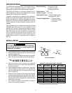
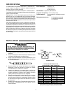
SPECIFICATIONS
Electrical Rating: 3 Amps @ 24 VAC
1 Amp @ 120 VAC
0.5 Amps @ 240 VAC
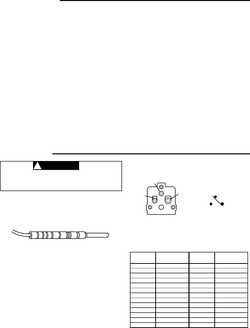
Switch Action: SPDT
Capillary Length: 48 Inches
Sensing Bulb Type: Universal Replacement
Thermocouple “slip-in”
Terminal Designations: 2 - Normally Open
3 - Normally Closed
4 - Common
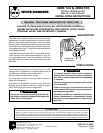
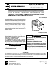
INSTALLATION
To avoid personal injury and/or property damage,
shut off gas and electric to heating system until
installation is complete.
1. Turn off gas and power until replacement is complete.
2. Remove defective flame sensor from pilot burner and
unplug from gas valve.
3. Align tip of defective flame sensor with tip of replace-
ment . Do not uncoil capillary of new flame sensor.
4. Note the location of the C-rings on the defective
sensor bulb and install C-rings on the replacement in
the same locations.
5. Insert replacement sensor in pilot burner. Uncoil only
enough capillary to allow sensor to be installed. Be
sure new sensing bulb is in the same position as the
unit it is replacing.
6. Carefully uncoil capillary of new sensor by grasping
capillary at switchcase and sensing bulb, then “stretch”
coil until switchcase reaches gas valve plug. Care-
fully align switchcase with gas valve socket and plug
flame sensor into valve.
7. Turn on gas and power. Cycle system a number of
times to insure proper operation.
CAUTION
!
OEM
MODEL NO.
3098-1
3098-111
3098-117
3098-120
3098-122
3098-124
3098-126
3098-127E1
3098-127E2
3098-130
3098-131
3098-134
3098-135
WHOLESALE
REPLACEMENT
3098-134
3098-134
3098-135
3098-135
3098-156
3098-156
3098-156
3098-134
3098-156
3098-156
3098-156
3098-134
3098-135
OEM
MODEL NO.
3098-136E1
3098-136E2
3098-137
3098-139
3098-140
3098-141
3098-142
3098-143
3098-144
3098-147
3098-148
3098-149
3098-153
WHOLESALE
REPLACEMENT
3098-134
3098-156
None
None
3098-140
3098-134
3098-156
3098-156
3098-156
3098-134
None
3098-156
3098-156
MERCURY FLAME SENSOR CROSS REFERENCE
Contact the O.E.M. (Original Equipment Manufacturer)
for replacements not listed in cross reference
Pin 2
(small)
Pin 3
(small)
Pin 4
(large)
24
3
Internal Schematic
4
(COM)
3
(COLD)
2
(HOT)
N.C.
N.O.