


INSTALLATION (CONT.)
2
perature lower than the dial setting.
4. The switch of the control may be mounted in any convenient
location provided that the ambient temperature surrounding
the switch does not exceed 150°F (66°C).
2. Care should be taken not to damage the capillary tubing
between the switch and bulb of the control. Do not kink the
capillary.
3. Do not dent or bend the control bulb as this will change the
control calibration and cause the control to cycle at a tem-
SETTING
The 2B61-186 has been provided with a graduated dial - 0 to
50°F, and knob to indicate setting of control. Adjust as needed
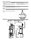
WIRING
All wiring should be done in accordance with local and national electrical codes and ordinances.
Follow any instructions provided by the equipment manufac-
turer.
The diagrams shown here represent typical wiring for these
controls.
LOAD
L2
L1
LINE
MAKE L1 “HOT”
ON 120V MODELS
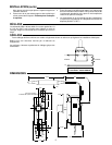
DIMENSIONS
0
10
20
30
40
50
F°
3/8"
1-1/4"
11/16"
1-9/16"
3-1/2"
1/4"
1/16"
5/16"
31/32"
2-1/2"
3/8"
3-3/4"
48"
.218" DIA. 2 HOLES
for particular usage.