


3
ATTACHING HUMIDITY CONTROL
TO ELECTRICAL BOX
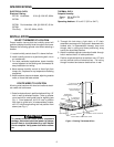
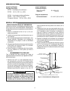
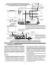
1. With wallplate still attached to humidity control and
wires through wallplate, connect leads together; one
black to Line, other black to Load and secure with wire
nuts. Connect green wire to electrical box ground.
(see Fig. 2)
2. Remove the two screws from the humidity control
cover and separate the humidity control from wallplate
by gripping the wallplate in one hand. Use the other
hand to pull gently at the top and bottom of the humidity
control.
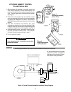
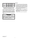
3. Push wire connections into electrical box, place
wallplate over electrical box (insuring wallplate is right
end up for vertical or horizontal) line up mounting holes
and fasten wallplate with screws supplied. (see Fig. 3)
4. Holding humidity control, push switch wires into elec-
trical box and snap humidity control onto wallplate.
Re-install the two screws removed in step 2.
5. Turn on power to system.
Figure 2.
Connecting Humidity
Switch Wires
CAUTION
Cover screws must be installed to prevent elec-
trical shock hazard.
MOUNTING
SCREWS
WALL
PLATE
Figure 3.
Attaching Wallplate
to Electrical Box.
HUMIDITY
CONTROL
MOUNTING
SCREWS
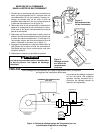
WIRING
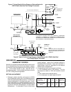
All wiring must conform with local and national electrical codes and ordinances.
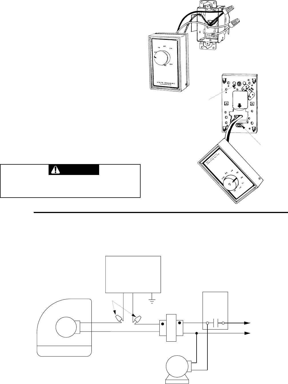
All wiring diagrams are for typical
systems only. Refer to equipment
manufacture's instructions for spe-
cific system wiring information.
FURNACE
BLOWER
MOTOR
24vAC
120vAC
TRANSFORMER
WIRE
NUTS
TYPE 2271/2272 HUMIDISTAT
Figure 4. Typical Furnace Humidifier Humidistat Wiring Diagram
FAN CONTROL
HOT
LINE
NEUTRAL
FURNACE
HUMIDIFIER
HUMIDITY
CONTROL
GREEN WIRE