The Fast Cool feature operates the cooling stages in the
same manner as Fast Heat, On or Off when the tempera-
ture is lowered below the room setting.
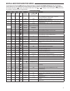
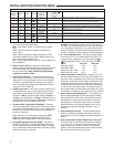
28. Select Remote Temperature Sensor Enabled – ON
enables a remote sensor connected to thermostat and
displays the sensor temperature in the clock digits. OFF
(default) indicates no remote sensor connected or en-
abled.
29. Selects Remote Sensor as Indoor or Outdoor – If 28
is enabled, select the remote to be Remote In (Indoor,
F145-1328) or Outdoor Remote (Outdoor, F145-1378).
Default is Remote In.
30. Select Local Sensor Disable – If 29 is selected Indoor,
the thermostat Local Sensor can be disabled so the
displayed temperature will be from the Remote Sensor.
Default is On LS. To disable the Local Sensor, change
selection to OFF LS.
31. Select Dual Fuel Feature (dF) – This feature is appli-
cable only in heat pump modes (HP1, HP2). Enables (On)
or disables (Off) dual fuel feature of thermostat.
32. Select Dual Fuel Temperature – With dF selected On
and outdoor remote sensor available, select the outdoor
temperature the thermostat will use to determine when to
switch to gas heat and shut down the compressor. When
the outdoor temperature falls below the selected tem-
perature the gas heat will begin. Default is 35°, but can be
set in the range of -5 to 50°. A lower setting will delay the
start of gas heat allowing cooler temperature in the home.
33. Select Dual Fuel Setting – With DF selected On and no
outdoor sensor, select the dF setting from 01-09. Fac-
tory default is 05. The dF setting influences when second
stage comes on. The factory default creates a separation
of approximately 1
o
F between stages. Increasing the set-
ting decreases the separation between stages. Decreas-
ing the value increases stage separation. This adjust-
ment allows a small change in the operation of your heat
pump system versus your auxiliary system relative to the
thermostat adjustment. The higher the number the sooner
the auxiliary stage energizes for better comfort. The lower
the number the longer period of time before auxiliary is
energized for more economy.
Note: This setting is not minutes or degrees. It is numeric
setting that will influence the internal thermostat calcula-
tion for staging.
34. Select Compressor Delay (Cd) – Applicable only in
heat pump modes (HP1, HP2). After the auxiliary heat is
turned on, the compressor(s) shut down is delayed for the
time selected (in seconds). This delay is factory set to 60,
but can be set in the range of 0 to 99.
35. Select Auxiliary Off (AO) – Applicable only In heat pump
modes (HP1, HP2) with outdoor sensor available. Select
the temperature that will inhibit the auxiliary heating
stage. As long as the outdoor temperature is above the
selected temperature, the auxiliary heat will not turn on.
The default setting is 60°, but can be set in the range of
-5 ° to 79°.
INSTALLER/CONFIGURATION MENU
If indoor temperature drops below 45° because of a pos-
sible heat pump malfunction, the thermostat will turn off
the pump and switch to Auxiliary heat. "Call for Service"
will display on screen.
There are two ways the thermostat will return to normal
heat pump operation:
• Pressanykeytoretrythepumpanderasethe"Call
for Service" icon.
• WhensetpointisachievedonAuxiliary,systemwill
return to heat pump operation on next call for heat.
36. Select Pre-Occupancy Purge (PP) – A selection of -O-
opens the damper at the Day (occupied) program period.
A selection of 1, 2 or 3 opens the damper early, 1, 2 or 3
hours before the Day (occupied) time in the program. This
allows 1, 2 or 3 hours of fresh air circulation before people
arrive.
37. Select Economizer or Damper Operation – This option
configures the thermostat A1 terminal for Commercial
Occupied Damper systems or Economizer systems. Com-
mercial Occupied Damper systems open a damper during
all Day (occupied) program time periods. Economizer
systems use the A1 terminal to open an economizer and
use outside air as the first cooling stage.
Select EC "Off" (Economizer Off) for Commercial Oc-
cupied Damper systems that require the A1 terminal to be
energized constantly during Day (occupied) program time
periods. With EC Off, the cooling terminals and stages
operate as follows: Y = Stage 1 cooling, Y2 = Stage 2 cool-
ing. A1 is energized constantly during Day (occupied) time
periods.
Select EC "On" (Economizer On) for Economizer systems
that use outside air for the first stage of cooling. With EC
On selected, the cooling terminals and stages operate
as follows: A1 = Stage 1 cooling, Y = Stage 2 cooling, Y2
= Stage 3 cooling. EC "On" also runs the first stage of
cooling (economizer) longer than a standard (compressor)
cooling stage because economizers are more efficient
with a longer run time.
41 & 42. Change UV Lamp – This feature allows the thermo-
stat to display the words "Change UV Lamp" (Call for
Service of UV bulb) after a set time of UV bulb operation.
This is a reminder to maintain your UV system at opti-
mum level of operation. When enabled, the factory set
interval for "Change UV Lamp" to be displayed is 350
days of UV bulb operation and can be adjusted in 25 day
increments. This should be adjusted with respect to the
bulb’s recommended maintenance schedule.
When "Change UV Lamp" is displayed, you can clear it
by pressing Clean Display.
43 & 44. Select Change Filter Run Time – This feature al-
lows thermostat to display "Change Filter" after a set
time of blower operation. This is a reminder to change
or clean your air filter. This time can be set from 25 to
1975 hours in 25 hour increments. A selection of OFF will
cancel this feature. When "Change Filter" is displayed,
you can clear it by pressing Clean Display. In a typical ap-
plication, 200 hours of run time is approximately 30 days.
8


