


INSTALLATION (cont’d)
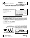
Transformer
THERMOSTAT
24 VAC
Line
Voltage
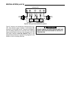
Figure 2. Wiring for two-transformer systems
RH W Y G RC
Heating
System
Cooling
System
Fan
Relay
Transformer
24 VAC
Line
Voltage
Figure 2 shows a two-transformer heating/cooling sys-
tem, with isolation relays installed in the heating (W),
cooling (Y), and fan (G) circuits. To simplify the diagram,
limit and safety switches are not shown here, although
they are found either in the low or high voltage circuit. Limit
and safety switches must be retained. Refer to the
equipment manufacturer’s system wiring diagram for the
location of limit and safety switches.
WARNING
!
DO NOT REMOVE OR WIRE AROUND LIMIT AND
SAFETY SWITCHES WHEN INSTALLING ISOLA-
TION RELAYS.