


3
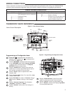
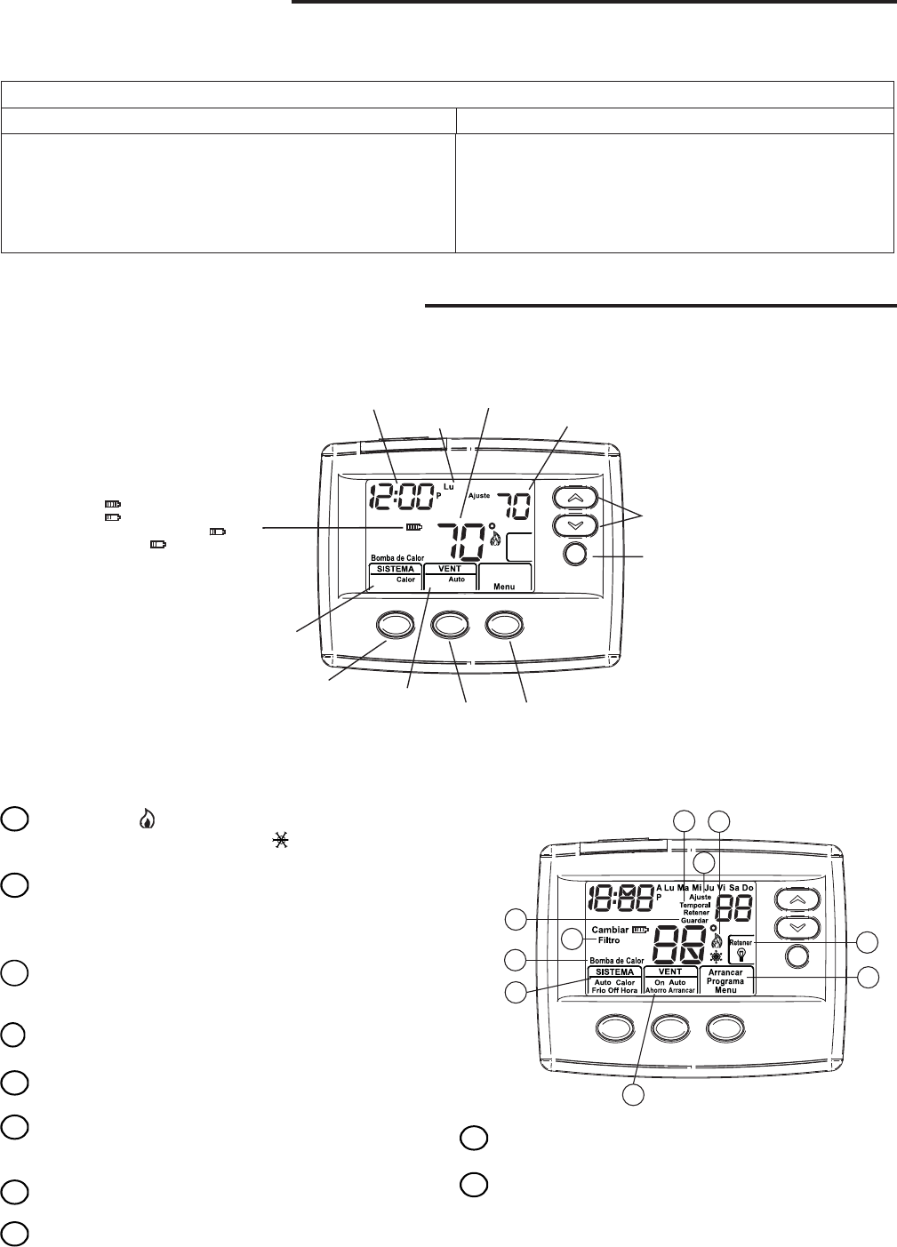
Displays the power level of the
2 “AA” batteries:
indicates good power level.
indicates batteries at about
half power. “Cambiar ”
(Change ) indicates batteries
are low and should be replaced
with 2 new premium brand “AA”
Alkaline batteries.
Time
Day of Week
Setting
Temperature
Room
Temperature
Temperature Up/Down
RETENER
Button
SISTEMA
Button
VENT
Button
SISTEMA
Indicator
VENT
Indicator
MENU/PROGRAMA/ARRANCAR
Button
Home Screen Description
Figure 4 – Home Screen Display
Figure 5 – Programming & Confi guration Items
10
1
2
3
4
5
6
7
8
9
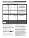
THERMOSTAT QUICK REFERENCE
9
Displays "Bomba de Calor" (Heat Pump) when
system is confi gured as Heat Pump thermostat.
10
Displays "Retener" (Hold) in programmable mode
when in "Retener" (Hold) mode. Displays Light Bulb
in non-programmable mode.
Programming and Confi guration Items
1
Flame icon ( ) is displayed when the system is in
CALOR mode. Snowfl ake icon (
) is displayed when
the system is in FRIO mode.
2
The word RETENER is displayed when the thermostat
is in the RETENER (Hold) mode. Temporal RETENER
is displayed when the thermostat is in a Temporal
RETENER (Temporary Hold) mode.
3
Displays "Cambiar Frio" (Change Filter) when the
system has run for the programmed fi lter time period
as a reminder to change or clean your fi lter.
4
Displays "Ajuste" (Set) for setpoint when in Run
Program mode.
5
Displays System Mode (Calor, Frio, Auto, Off) or Hora
(Time) in menu mode.
6
Displays Fan Mode (On, Auto) or "Arrancar" (Run) in
Menu mode of "Ahorra" (Saving) in Cool Savings
TM
Mode.
7
Displays "Arrancar Programa" (Run Schedule),
"Programa" (Schedule), or "Menu".
8
Displays "Guardar" (Save) when Cool Savings
TM
is
working.
Refer to equipment manufacturers' instructions for specifi c system wiring information. After wiring, see CONFIGURATION
section for proper thermostat confi guration. Refer to 37-6754 for 1F80-0471/1F86-0471 wiring diagram specifi cations.
WIRING CONNECTIONS
TERMINAL DESIGNATION DESCRIPTIONS
Terminal
Designation Description
Terminal
Designation Description
O/B.................
Y......................
W....................
G.....................
(SS) Power closed for 3 wire zone
(HP) Changeover valve for heat pump
Compressor Relay
Heat Relay
Fan Relay
RH...................
RC...................
C.....................
Power for Heating
Power for Cooling
Common wire from secondary side
of cooling system transformer or
heat only system transformer