


7
Technical Data
R
C
24 VAC
120 VAC
Hot
Neutral
THERMOSTAT
SYSTEM
G W
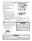
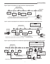
Figure 2. Typical wiring diagram for single transformer single stage systems
TRANSFORMER
(Class II Current Limited)
Changeover
Relay*
YO/B
Compressor
Contactor
* Changeover Relay is energized in COOL when O/B switch is in the “O” position
Changeover Relay is energized in HEAT when O/B switch is in the “B” position
Heat Relay
Fan
Relay
Optional
Optional Jumper for
Single Stage Heat Pump
R
C
24 VAC
120 VAC
Hot
Neutral
THERMOSTAT
SYSTEM
G W
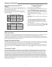
Figure 3. Typical wiring diagram for two transformer single stage systems with NO safety circuits
TRANSFORMER
(Class II Current Limited)
Changeover
Relay*
YO/B
Compressor
Contactor
* Changeover Relay is energized in COOL when O/B switch is in the “O” position
Changeover Relay is energized in HEAT when O/B switch is in the “B” position
Heat Relay
Fan
Relay
Optional
Limit or
Safety
Switches
TWO COMMONS MUST
BE JUMPERED TOGETHER!
HOT
NEUTRAL
120 VAC
24 VAC
CUT AND
TAPE OFF!
If safety circuits are in only one of
the systems, remove the transformer
of the system with NO safety circuits.
NOTE
Optional Jumper for
Single Stage Heat Pump
R
C
24 VAC
120 VAC
Hot
Neutral
THERMOSTAT
SYSTEM
G W
Figure 3. Typical wiring diagram for two transformer single stage systems with NO safety circuits
TRANSFORMER
(Class II Current Limited)
Changeover
Relay*
YO/B
Compressor
Contactor
* Changeover Relay is energized in COOL when O/B switch is in the “O” position
Changeover Relay is energized in HEAT when O/B switch is in the “B” position
Heat Relay
Fan
Relay
Optional
Limit or
Safety
Switches
TWO COMMONS MUST
BE JUMPERED TOGETHER!
HOT
NEUTRAL
120 VAC
24 VAC
CUT AND
TAPE OFF!
If safety circuits are in only one of
the systems, remove the transformer
of the system with NO safety circuits.
NOTE
Optional Jumper for
Single Stage Heat Pump
R
CG W
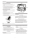
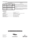
Figure 4. Typical wiring diagram for two transformer single stage systems with safety circuits in BOTH systems
Changeover
Relay*
YO/B
Compressor
Contactor
* Changeover Relay is energized in COOL when O/B switch is in the “O” position
Changeover Relay is energized in HEAT when O/B switch is in the “B” position
Heat
Relay
Fan
Relay
Optional
TWO COMMONS MUST
BE JUMPERED TOGETHER!
24 VAC 120 VAC
HOT
NEUTRAL
THERMOSTAT
SYSTEM
HOT
NEUTRAL
120 VAC
Limit or
Safety
Switches
Limit or
Safety
Switches
Limit or
Safety
Switches
24 VAC
Limit or
Safety
Switches
COMMON
COMMON
Auxiliary
Heating
Transformer
(Class II
Current Limited)
Heat Pump Tr ansformer
(Class II Current Limited)
24 VAC
ACCESSORY
RELAY N.O.
CONTACT
Polarity must be observed. If the HOT side of the
second transformer is jumpered to the COMMON side
of the first transformer a short will be made. Damage
to equipment will occur when power is restored.
NOTE
The accessory relay scheme
is required when safety
circuits exist in both systems.
NOTE
Optional Jumper for
Single Stage Heat Pump
R
CG W
Figure 4. Typical wiring diagram for two transformer single stage systems with safety circuits in BOTH systems
Changeover
Relay*
YO/B
Compressor
Contactor
* Changeover Relay is energized in COOL when O/B switch is in the “O” position
Changeover Relay is energized in HEAT when O/B switch is in the “B” position
Heat
Relay
Fan
Relay
Optional
TWO COMMONS MUST
BE JUMPERED TOGETHER!
24 VAC 120 VAC
HOT
NEUTRAL
THERMOSTAT
SYSTEM
HOT
NEUTRAL
120 VAC
Limit or
Safety
Switches
Limit or
Safety
Switches
Limit or
Safety
Switches
24 VAC
Limit or
Safety
Switches
COMMON
COMMON
Auxiliary
Heating
Transformer
(Class II
Current Limited)
Heat Pump Transformer
(Class II Current Limited)
24 VAC
ACCESSORY
RELAY N.O.
CONTACT
Polarity must be observed. If the HOT side of the
second transformer is jumpered to the COMMON side
of the first transformer a short will be made. Damage
to equipment will occur when power is restored.
NOTE
The accessory relay scheme
is required when safety
circuits exist in both systems.
NOTE
Optional Jumper for
Single Stage Heat Pump