


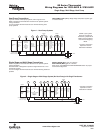
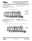

Figure 3 – Single Stage or Multi-Stage System (No Heat Pump)
with Two Transformers
Single
Stage 1
(SS1)
Multi-
Stage 2
(MS2)
O
Energized
Constantly
in
Cool Mode
B
Energized
Constantly
in Heat, Off,
Emergency
Mode
No
Output
Cool
Mode
2nd
Stage
Cool Mode
1st Stage
Blower/
Circulator
Fan Energized
on Call for
Cool (and
Heat if
configured
for Electric
Heat)
No Output
Heat Mode
2nd Stage
Heat
Mode
1st Stage
Optional
24 Volt
(Com-
mon)
Fault
Indicator
(NOT
USED)
24 Volt
(Hot)
Cool
System
Y
G
W/E
C
L
RC
CLASS II
TRANSFORMER
HOT
24VAC
NEUTRAL
120VAC
24 Volt
(Hot)
Heat
RH
120VAC
Remove Jumper Wire
between RH & RC
HOT
24VAC
NEUTRAL
CLASS II
TRANSFORMER
HEATING
COOLING
Y2
W2
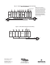
Jumper
O/B
Single Stage
3-wire
Zone Valve
application
Blower/Circulator
Fan Energized
Opens
Valve
(4)
Constant
24 Volt
(Com-
mon)
24 Volt
(Hot)
Cool
System
6
Y
W
C
RC
CLASS II
TRANSFORMER
HOT
24VAC
NEUTRAL
120VAC
24 Volt
(Hot)
Heat
(5)
RH
G
Jumper
Closes
Valve
(6)
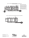
NOTE: If continuous backlight or
hardwired power input are desired but
do not function in both HEAT and COOL
modes, cut the heating transformer 24V
wires and tape off. Connect the neutral
circuit disconnected from the heating
transformer to the neutral circuit of the
cooling transformer. Disconnect the wire
to the RH terminal and install a jumper
between RH and RC. Depending on
the system requirements, replace the
cooling transformer with a 75VA class II
transformer if needed.
Figure 4 – 3-Wire (SPDT) Heat Only Zone Valve Wiring
White-Rodgers is a division
of Emerson Electric Co.
The Emerson logo is a
trademark and service mark
of Emerson Electric Co.
St. Louis, Missouri
www.white-rodgers.com