


2
REMOVE OLD THERMOSTAT
1. Shut off electricity at the main fuse box until installation is
complete. Ensure that electrical power is disconnected.
2. Remove the front cover of the old thermostat. With wires
still attached, remove wall plate from the wall. If the old
thermostat has a wall mounting plate, remove the thermostat
and the wall mounting plate as an assembly.
3. Identify each wire attached to the old thermostat using the
labels enclosed with the new thermostat.
4. Disconnect the wires from old thermostat one at a time. DO
NOT LET WIRES FALL BACK INTO THE WALL.
5. Install new thermostat using the following procedures.
PRE-INSTALLATION SET-UP
1. Remove the packing material from the thermostat.
2. This thermostat is configured from the factory to operate a
heat/cool, fossil fuel (gas, oil, etc.), forced air system with up
to 2 stages of heat and 2 stages of cool. It is configured
correctly for any system that DOES NOT require the thermo-
stat to energize the fan on a call for heat.
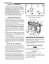
If your system is an electric heat or heat-pump system that
REQUIRES the thermostat to turn on the fan on a call for
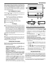
heat, locate the GAS/ELECTRIC switch on the back of the
thermostat (see fig. 1) and switch it to the ELECTRIC
position. This will allow the thermostat to energize the fan
immediately on a call for heat. If you are unsure if the heating/
cooling system requires the thermostat to control the fan,
contact a qualified heating and air conditioning service
person.
3. One jumper is located on the back of the thermostat, so that
you may customize the thermostat to meet your individual
preference (see fig. 1). In most applications, the factory
jumper settings provide the most comfortable and conve-
nient thermostat operation.
Jumper wire W905 determines how fast the system cycles
on and off, based on temperature change. As shipped from
the factory, the thermostat will maintain a very consistent
room temperature, usually within 1°F of the thermostat
setting. To achieve a slower on and off cycle, providing a
slightly wider temperature span, cut and separate jumper
wire W905.
INSTALLING THE THERMOSTAT
1. Gently remove the cover by pulling it straight off the base.
Forcing or prying on the unit may cause damage to the unit.
2. Remove the battery tab. With the batteries installed, the
Armchair Programming feature allows you to program the
thermostat before installing it on the wall.
3. Pull wires through the hole in the thermostat base and place
the base over the hole in the wall. Mark mounting hole
locations on the wall using the base as a template.
4. Move the base out of the way. Drill mounting holes.
5. Fasten the base loosely to the wall, as shown in fig. 2, using
two mounting screws. Place a level against the bottom of the
base, adjust until level, and then tighten the screws. (Level-
ing is for appearance only and will not affect thermostat
operation.) If you are using existing mounting holes, or if the
holes drilled are too large and do not allow you to tighten the
base snugly, use plastic screw anchors to secure the base.
INSTALLATION
Figure 1. Back of thermostat base
W905
CUT FOR
LONGER
CYCLES
GAS ELECTRIC
Figure 2. Thermostat base
Mounting
holes
Screw anchors
Alkaline batteries (3 “AA”–
install “+” ends to the left)
C
W2
R
G
Y
Y2
B
O
W
Reset
button
NOTE
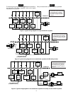
6. Check that the system is turned off. Connect the wires
beneath the terminal screws on the base using the appropri-
ate wiring diagram (see figs. 3 through 5).
7. Push excess wire into wall and plug hole with a fire-resistant
material (such as fiberglass insulation) to prevent drafts from
affecting thermostat operation.
CHECK THERMOSTAT OPERATION
If at any time during testing, your system does not operate
properly, contact a qualified serviceperson.
Fan Operation
1. Turn on power to the system.
2. Press SYSTEM button until the system is OFF.
3. Move FAN switch to ON. The blower should begin to operate.
4. Move FAN switch to AUTO position. The blower should stop
within a short period of time.
(Instructions continue on page 4.)