


3
C* R
Y2
Compressor
Contactor
Stage 1
Heat
Relay
Stage 1
Heat
Relay
Stage 2
Thermostat
Control
Circuit
24 VAC 120 VAC
Hot
Neutral
THERMOSTAT
SYSTEM
Y W
W2
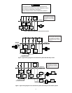
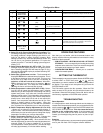
Figure 2. Typical wiring diagram for single transformer systems
Fan
Relay
G
TRANSFORMER
Compressor
Contactor
Stage 2
* The 24 Volt neutral connection
to terminal C on the thermostat
is not required if you replace
the batteries once a year with
fresh “AA” Energizer
®
alkaline
batteries.
C* R
Y2
Compressor
Contactor
Stage 1
Heat
Relay
Stage 1
Heat
Relay
Stage 2
Thermostat
Control
Circuit
24 VAC 120 VAC
Hot
Neutral
THERMOSTAT
SYSTEM
Y W
W2
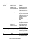
Figure 3. Typical wiring diagram for two-transformer systems with NO safety circuits
Fan
Relay
G
TRANSFORMER
Compressor
Contactor
Stage 2
24 VAC120 VAC
Hot
Neutral
TRANSFORMER
TWO COMMONS MUST
BE JUMPERED TOGETHER!
CUT AND
TAPE OFF!
* The 24 Volt neutral connection
to terminal C on the thermostat
is not required if you replace
the batteries once a year with
fresh “AA” Energizer
®
alkaline
batteries.
C* R
Y2
Compressor
Contactor
Stage 1
Heat
Relay
Stage 1
Heat
Relay
Stage 2
Thermostat
Control
Circuit
Limit or
Safety
Switches
Limit or
Safety
Switches
Limit or
Safety
Switches
Limit or
Safety
Switches
24 VAC 120 VAC
Hot
Common
Common
Neutral
THERMOSTAT
SYSTEM
Y W
W2
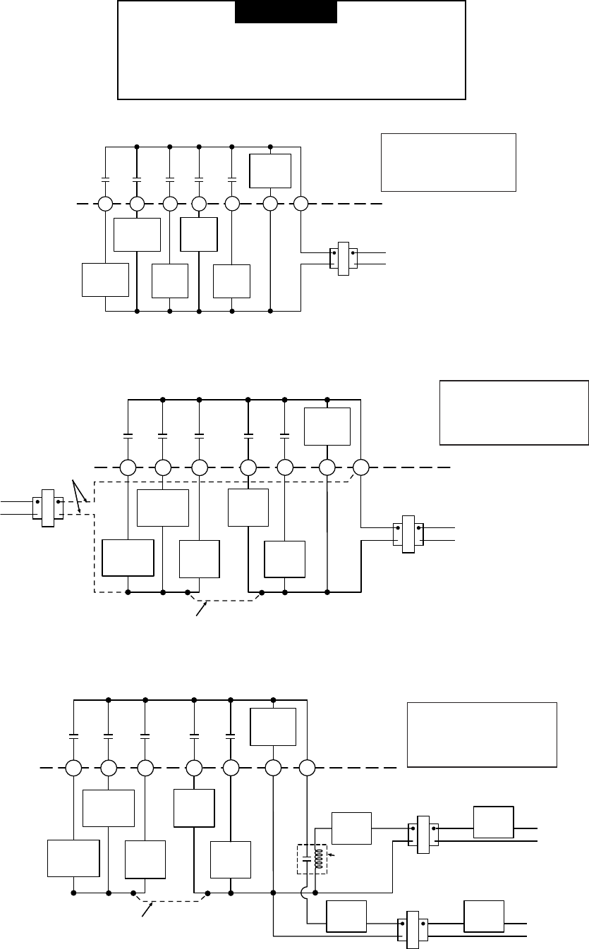
Figure 4. Typical wiring diagram for two-transformer systems with safety circuits in BOTH systems
Fan
Relay
G
HEATING
TRANSFORMER
Compressor
Contactor
Stage 2
24 VAC 120 VAC
Hot
Neutral
COOLING
TRANSFORMER
TWO COMMONS MUST
BE JUMPERED TOGETHER!
24 VAC
Accessory
Relay N.O.
Contact
* The 24 Volt neutral connection
to terminal C on the thermostat
is not required if you replace
the batteries once a year with
fresh “AA” Energizer
®
alkaline
batteries.
▲
! NOTE
The following wiring diagrams show typical terminal
identification and wiring. For proper installation, refer to
the original manufacturer’s instructions.
Relay contacts shown are thermostatically operated.