


3
RH
Y
24 VAC
120 VAC
Hot
Neutral
THERMOSTAT
SYSTEM
G W
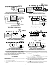
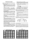
Figure 8. Typical wiring diagram for
heat/cool, 5-wire, two-transformer systems
HEATING TRANSFORMER
Heating
System
Fan
Relay
Cooling
System
RC
24 VAC
120 VAC
Hot
Neutral
COOLING TRANSFORMER
OB
RH
Y
24 VAC
120 VAC
Hot
Neutral
THERMOSTAT
SYSTEM
G W
Figure 7. Typical wiring diagram for
heat/cool, 4-wire, single transformer systems
TRANSFORMER
Heating
System
Fan
Relay
Cooling
System
RC
JUMPER
WIRE
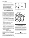
RED jumper wire (provided
with thermostat) must be
connected between thermo-
stat's RH and RC terminals
for proper thermostat oper-
ation with this system.
NOTE
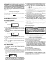
OB
RW
B
W
R
Thermostat
3-wire Series 10
Primary Control
(located at furnace)
Add jumper wire
(not provided with thermostat)
Figure 4. Typical wiring diagram for
3-wire SERIES 10 heating systems
Furnace
Jumper wire must be
added between R and B
terminals on the primary
control (jumper wire not
provided with thermostat).
NOTE
RH
Y
24 VAC
120 VAC
Hot
Neutral
THERMOSTAT
SYSTEM
G W
Figure 5. Typical wiring diagram for
heat only, 3-wire, single transformer systems
TRANSFORMER
Heating
System
Fan
Relay
Y
RC
JUMPER
WIRE
RED jumper wire (provided
with thermostat) must be
connected between thermo-
stat's RH and RC terminals
for proper thermostat oper-
ation with this system.
NOTE
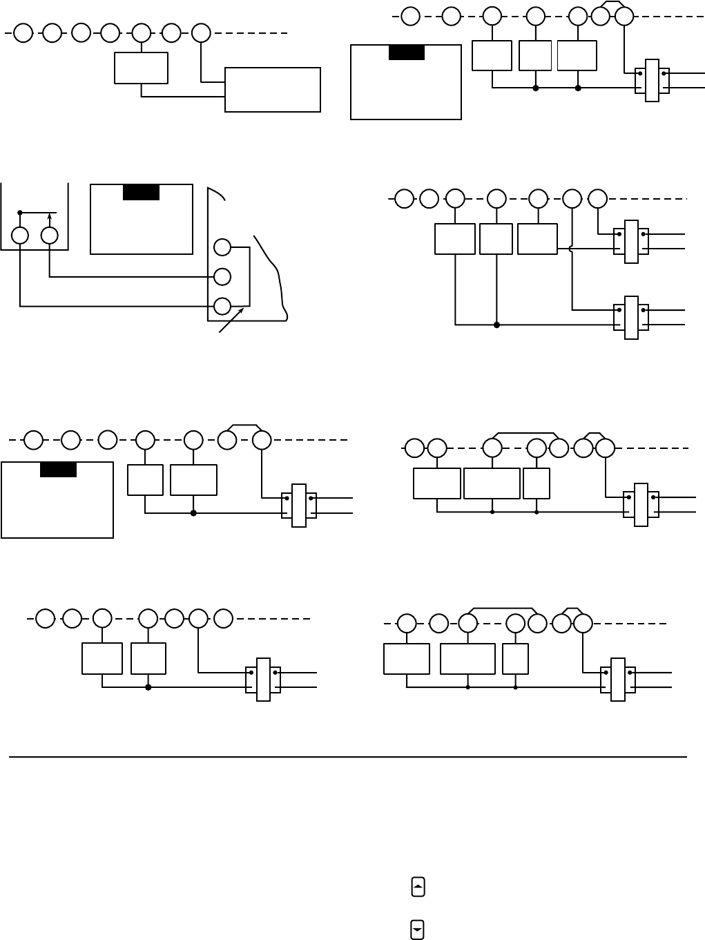
OB
RH
Y
24 VAC
120 VAC
Hot
Neutral
THERMOSTAT
SYSTEM
G W
Figure 10. Typical wiring diagram for
heat pump with heat active reversing valve
TRANSFORMER
Reversing
Valve*
RCOB
JUMPER
WIRE
Compressor
Contactor
JUMPER
WIRE
* Reversing valve is energized when the
system switch is in the HEAT position
Fan
Relay
RH
Y
THERMOSTAT
SYSTEM
G W
Figure 3. Typical wiring diagram for heating only,
2-wire, single transformer systems or millivolt systems
Heating
System
RCOB
24 VAC Transformer
or
Thermopile
RH
Y
24 VAC
120 VAC
Hot
Neutral
TRANSFORMER
THERMOSTAT
SYSTEM
G W
Figure 6. Typical wiring diagram for
cool only, 3-wire, single transformer systems
Cooling
System
Fan
Relay
RCOB
RH
Y
24 VAC
120 VAC
Hot
Neutral
THERMOSTAT
SYSTEM
G W
Figure 9. Typical wiring diagram for
heat pump with cool active reversing valve
TRANSFORMER
Reversing
Valve*
RCOB
JUMPER
WIRE
Compressor
Contactor
JUMPER
WIRE
* Reversing valve is energized when the
system switch is in the COOL position
Fan
Relay
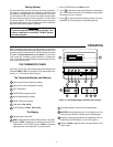
CHECK THERMOSTAT OPERATION
If at any time during testing your system does not operate
properly, contact a qualified serviceperson.
Fan Operation
If your system does not have a G terminal connection, skip to
Heating System.
1. Turn on power to the system.
2. Move fan switch to ON position. The blower should begin to
operate.
3. Move fan switch to AUTO position. The blower should stop
immediately.
Heating System
1. Move SYSTEM switch to HEAT position. If the heating
system has a standing pilot, be sure to light it.
2. Press
to adjust thermostat setting above room tempera-
ture. The heating system should begin to operate.
3. Press to adjust temperature setting below room tempera-
ture. The heating system should stop operating.