


3
RH
Y
24 VAC
120 VAC
Hot
Neutral
THERMOSTAT
SYSTEM
G W
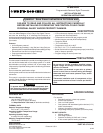
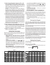
Figure 5. Typical wiring diagram for
heat/cool, 5-wire, two-transformer systems
with common connection (required)
HEATING
TRANSFORMER
Heating
System
Fan
Relay
Cooling
System
RC
24 VAC
120 VAC
Hot
Neutral
COOLING TRANSFORMER
OBC
RH
Y
24 VAC
120 VAC
Hot
Neutral
THERMOSTAT
SYSTEM
G W
Figure 4. Typical wiring diagram for
heat/cool, 4-wire, single transformer systems
with common connection (required)
TRANSFORMER
Heating
System
Fan
Relay
Cooling
System
RC
JUMPER
WIRE
OC B
RED jumper wire (provided with thermostat) must be
connected between thermostat RH and RC terminals
for proper thermostat operation with this system.
NOTE
RH
24 VAC
120 VAC
Hot
Neutral
THERMOSTAT
SYSTEM
G W
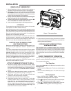
Figure 2. Typical wiring diagram for
heat only, 3-wire, single transformer systems
with common connection (required)
TRANSFORMER
Heating
System
Fan
Relay
YC
RC
JUMPER
WIRE
OB
RH
Y
24 VAC
120 VAC
Hot
Neutral
THERMOSTAT
SYSTEM
G W
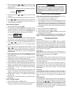
Figure 7. Typical wiring diagram for heat pump
with reversing valve energized in HEAT
with common connection (required)
TRANSFORMER
Reversing
Valve*
RCOBC
JUMPER
WIRE
Compressor
Contactor
JUMPER
WIRE
* Reversing valve is energized when the
system switch is in the HEAT position
Fan
Relay
RH
Y
24 VAC
120 VAC
Hot
Neutral
TRANSFORMER
THERMOSTAT
SYSTEM
G W
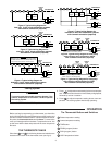
Figure 3. Typical wiring diagram for
cool only, 3-wire, single transformer systems
with common connection (required)
Cooling
System
Fan
Relay
RCOB
C
JUMPER
WIRE
RH
Y
24 VAC
120 VAC
Hot
Neutral
THERMOSTAT
SYSTEM
G W
Figure 6. Typical wiring diagram for heat pump
with reversing valve energized in COOL
with common connection (required)
TRANSFORMER
Reversing
Valve*
RCOBC
JUMPER
WIRE
Compressor
Contactor
JUMPER
WIRE
* Reversing valve is energized when the
system switch is in the COOL position
Fan
Relay
Before you begin programming your thermostat, you should be
familiar with its features and with the display and the location and
operation of the thermostat buttons. Your thermostat consists of
two parts: the thermostat cover and the base. To remove the
cover, pull it straight out from the base. To replace the cover, line
up the cover with the base and press until the cover snaps onto
the base.
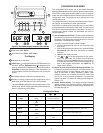
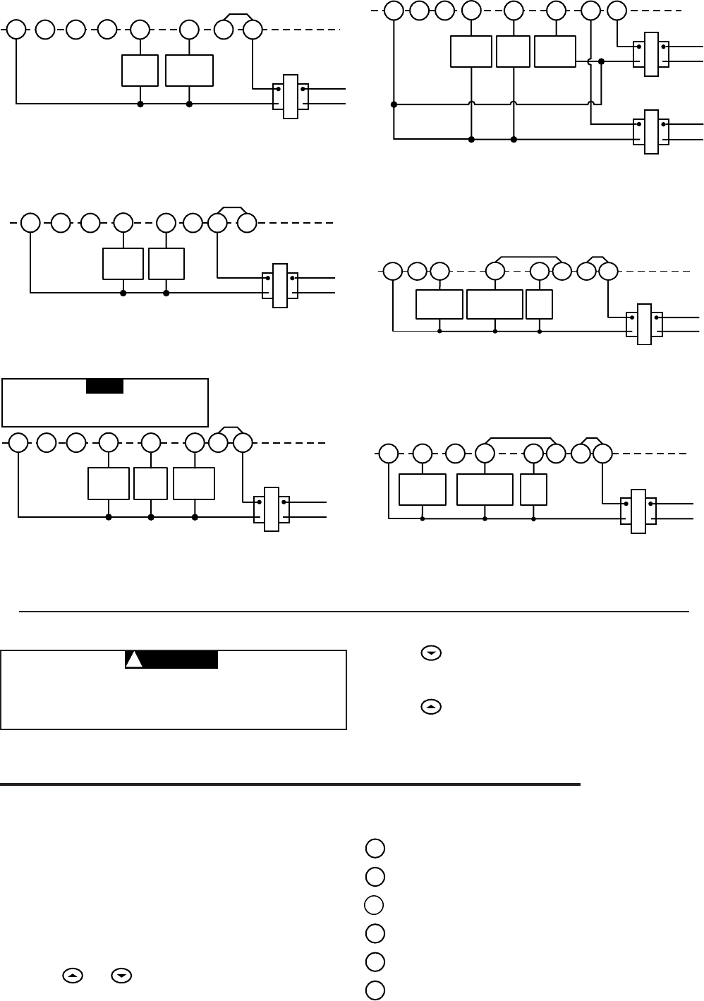
THE THERMOSTAT BASE
Other than and , the following buttons and switches are
located on the bottom of the thermostat cover (see fig. 8).
CAUTION
!
OPERATION
Cooling System
To prevent compressor and/or property damage, if the
outdoor temperature is below 50°F, DO NOT operate
the cooling system.
1. Move SYSTEM switch to COOL position.
2. Press
to adjust thermostat setting below room tempera-
ture. The blower should come on immediately on high speed,
followed by cold air circulation
3. Press to adjust temperature setting above room tem-
perature. The cooling system should stop operating.
The Thermostat Buttons and Switches
1
Raises temperature setting.
2
Lowers temperature setting.
3
TIME button.
4
PRGM (program) button.
5
RUN (program) button.
6
HOLD temperature button.