


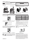

Make the appropriate connections to the thermostat as per diagram
below. The wires are non-polarized so either wire can be connected
to either terminal.
Keep the air vents of the thermostat clean and unobstruct-
ed at all times. Failure to do so can cause harm to your
thermostat.
OPERATION
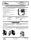
Slide thermostat switch to position. The thermostat normally displays
the actual ambient temperature.
To view the setpoint temperature, press the or button once. The
icon appears and the thermostat displays the setpoint temperature.
To change the setpoint, press the
or button to raise or lower the
temperature until the desired setpoint is reached.
To turn the backlight on, press the button, or the or button
once.
To change the thermostat installer confi guration, press and hold the
button for 5 seconds. The features and (defaults) are selected by
pressing the button once to scan the installer confi guration selec-
tions. The defaults are changed with the or button. (Please refer
to the following table for the selections of your choice.)
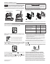
Place the thermostat cover back onto the base hinge and close cover.
Install screw to secure cover.
Align and affi x the base to the electrical junction box or the optional
adapter plate using two 6-32 pan head screws.
The thermostat displays the percentage of power usage (in "PC" mode
only) required to maintain the desired temperature. For example:
100% power usage
70% power usage
30% power usage
Default Options
Backlight LO (On) LF (Off)
Display Reading Adjustment* H0.0 L3.0 to H3.0
Proportional Control** PO (On) PF (Off)
Anticipation***
AL(2000-4000 W) AS (500-2000 W)
Temperature Scale SC (Celsius) SF (Fahrenheit)
* Adjusts room temperature display higher or lower to agree with a
previous thermostat.
** Proportional Control allows the thermostat to modulate depending
on power usage.
***Adjusts your thermostat anticipation based on the room and base-
board heater size, e.g., in a room with a 3500 W baseboard heater,
set your thermostat anticipation to AL.
The thermostat will save the setpoint temperature and installer confi gu-
ration selections permanently, even after power outages.
To reset the thermostat, press the
, , and buttons
simultaneously.
To suspend the thermostat operation, slide the thermostat switch to
the position. In this position, the thermostat still has power but the
display is turned off.
4 Wire Installation
2 Wire Installation
INSTALLATION (cont.)
Heating Element Thermal Protection
Most heating elements have a protection device that activates when
overheated. It is possible that if the device is worn out, it becomes
more sensitive. This device has a chance of being activated when
the heating element is on for a long period of time. When the thermal
protection is activated, the electrical power ceases to supply the
thermostat, and its display is turned off for a few minutes. The same
phenomenon exists with a mechanical thermostat but nothing could
indicate it. A thermal protection that opens too often can cause the
thermostat to poorly regulate temperature and should be replaced by
an electrician or the heating element manufacturer.
The Emerson logo is a
trademark and a service mark
of Emerson Electric Co.
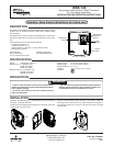
NOTE
Use with copper conductors only. Use wire con-
nectors approved for 12 AWG only.
CAUTION