


5
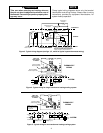
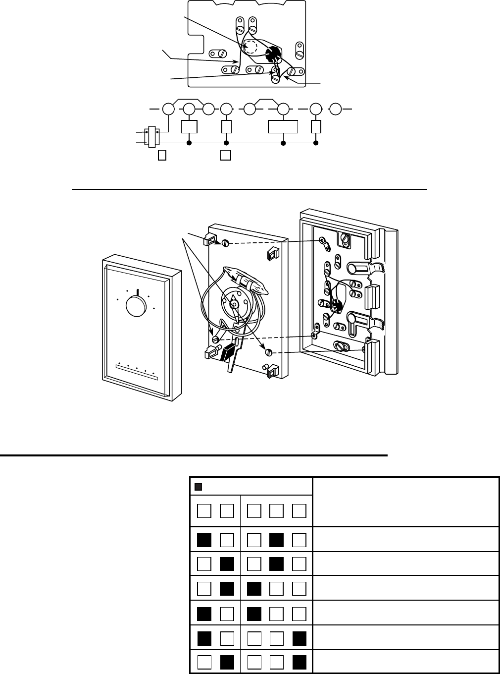
This thermostat is easy to operate. Fig. 8
shows how the heating/cooling system
and fan operate when the switches are in
various positions. Use the system switch
to select either heating or cooling, or to
turn the heating/cooling system off. Use
the fan switch to control fan operation.
When the fan switch is in the AUTO
position, the fan will cycle with the heating
or cooling system (the fan will not run if the
system switch is in the OFF position and
the fan switch is in the AUTO position).
When the fan switch is in the ON position,
the fan will run continuously, regardless
of system switch position (even if the
system switch is set to OFF, the fan will
run if the fan switch is in the ON position).
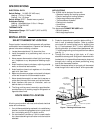
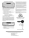
Figure 7. Attach thermostat to subbase
Captive
screws
COVER
THERMOSTAT
BASE
S
Y
S
T
E
M
C
O
O
L
O
F
F
H
E
A
T
A
U
T
O
O
N
F
A
N
G
RC
Y
W
B
ARH
O
50
60
70
80
90
50
60
70
80
90
WHITE-RODGERS
GRC
Y
W
B
A
RH
O
THERMOSTAT
WIRING
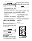
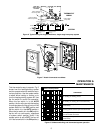
Figure 6. Typical wiring for single transformer, single stage heat pump system
KEEP THIS
AREA CLEAR
OF WIRES!
W BO YG A
24 VAC
120 VAC
Hot
Neutral
TRANSFORMER
Compressor
Relay
Fan
Relay
* * *
Factory-Installed Jumper
SYSTEM
* * *
Terminal energized
in cooling
Terminal energized
in heating
Field-installed
Jumper Wire
RH
Field-Installed Jumper
RC
Factory-installed
Red Jumper Wire
Factory-installed
Yellow Jumper Wire
OPERATION &
MAINTENANCE
FAN
AUTO ON
SYSTEM
COOL OFF HEAT
Shows switch position
OPERATION
No heating; no cooling; no fan
No heating; no cooling; fan runs continuously
Cooling system cycles from thermostat; fan runs
continuously
Cooling system and fan cycle from thermostat
Heating system cycles from thermostat; fan cycles
from fan control on furnace
Heating system cycles from thermostat; fan runs
continuously
Figure 8. Subbase switching and thermostat/system operation