


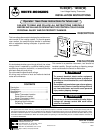


3
WR
secure base. If holes in wall are too large and do not
allow you to tighten the mounting screws securely, use
plastic expansion plugs.
8. Snap cover on the thermostat base and set tempera-
ture lever to desired setpoint.
9. Turn on electrical power to system.
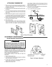
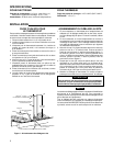
ATTACHING THERMOSTAT
1. Remove cover from thermostat by gripping the base in
one hand. Use the other hand to pull gently at the top
or bottom of the cover.
2. Carefully remove the shipping protective packing from
the switch.
3. Pull wires through the opening in the thermostat base
and connect wires beneath the terminal screws (see
Fig. 2 & 3).
4. Push excess wiring back into wall and plug hole with
fire resistant material (such as fiberglass insulation) to
prevent drafts from affecting thermostat operation.
5. Position thermostat base over hole in wall and mark
mounting hole location on wall.
6. Drill mounting hole.
7. Fasten base loosely to wall using mounting screws.
Place a level against the top of the thermostat base,
adjust until level, and tighten mounting screws to
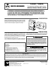
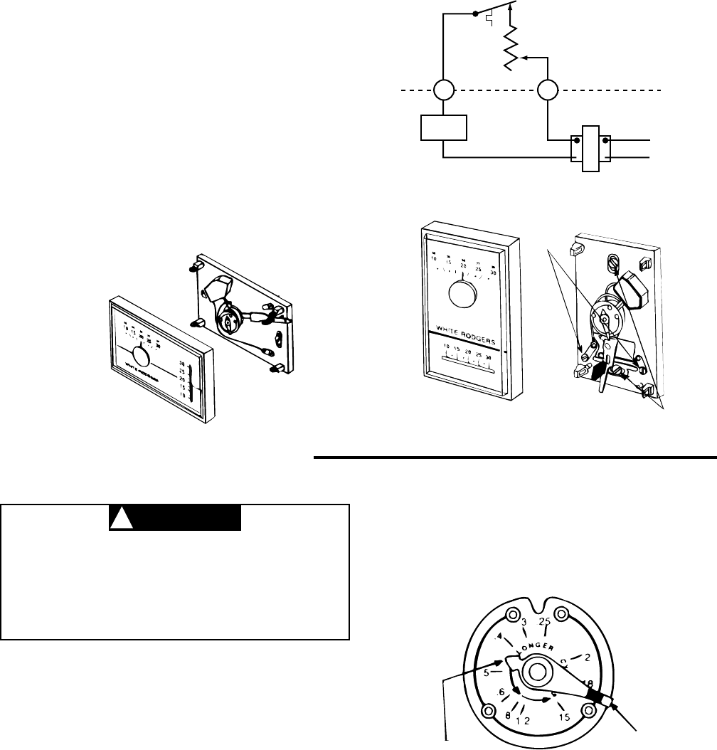
ADJUSTING HEAT ANTICIPATOR
The adjustable heat anticipator WILL BURN OUT
if 25 VAC is applied directly to the thermostat
because of incorrect wiring or by shorting out the
primary control during testing. This may cause
personal injury and/or property damage.
This thermostat is equipped with an adjustable heat
anticipator and was preset at the factory to provide
satisfactory operation of the heating system under normal
conditions. If additional adjustments are necessary, they
may be made as follows (See Fig. 4).
If thermometer reading on cover does not match the
thermostat:
1. Remove thermostat cover.
2. If heat cycle is too long, set heat anticipator to a slightly
lower dial setting (1/2 division).
3. If heat cycle is too short, set heat anticipator to a
slightly higher dial setting (1/2 division).
4. Replace thermostat cover.
Arrow points to the
matched current rating
of the primary control
Move this lever to
adjust heat
anticipator
.
.
.
.
.
.
Figure 4. Anticipator Adjustment
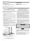
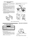
Figure 2. Wiring Diagram
Heat
Anticipator
(adjustable)
THERMOSTAT
SYSTEM
Hot
24 VAC 120 VAC
Neutral
Heating
System
Terminal
screws
Mounting
screws
THERMOSTAT
BASE
Figure 3. Parts of Thermostat
THERMOSTAT
BASE
COVER
COVER
ADJUSTMENT & MAINTENANCE
CAUTION
!