


3
INSTALLATION (cont’d)
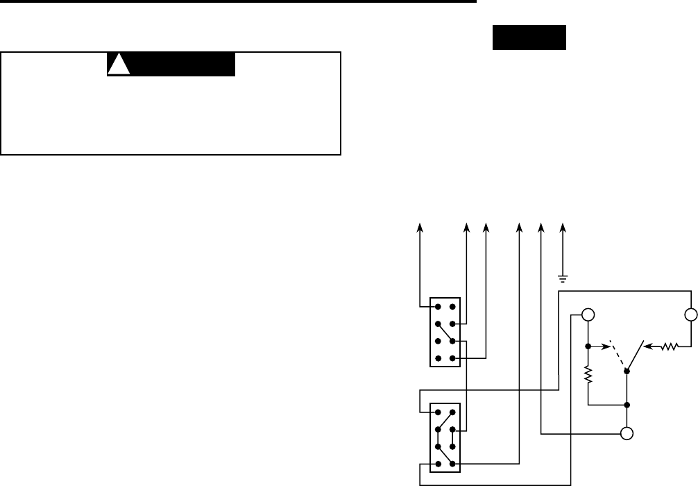
WIRING
To prevent electrical shock and/or equipment
damage, disconnect electric power to system at
main fuse or circuit breaker box until installation
is complete.
- Thermostat cycles both fan and valve
- Thermostat cycles fan only (if valve is not used,
tape orange lead)
- System “OFF” breaks both valve and fan circuits
- Thermostat cycles valve only with continuous
fan (interchange valve and L1 leads)
TAN
BLUE
COOL
COOL
HEAT
HEAT
VALVE
L1 GNDHIGH
HIGH
FAN
SWITCH
SYSTEM
SWITCH
MED
FAN
MED
OFF
LOW
LOW
RED
BLUE
RED
ORANGE
BLACK
GREEN
12
3
1A11-2 5-wire for single valve,
manual heat/cool changeover
CAUTION
!
NOTE
This typical wiring diagram shows only the terminal
identification and wiring hookup. Always refer to wiring
instructions, provided by equipment manufacturer, for
system hookup operation.
All wiring should be done according to local and national
electrical codes and ordinances.