


2
INSTALLATION CONT.
To set the dial, simply move it so that the indicating line on
the case points to the temperature at which the contacts
are to open as the temperature drops.
SETTING THE DIAL
TO LINE SWITCH
AND POWER SUPPLY
TEMPERATURE
CONTROL
SUCTION
PRESSURE
CONTROL
HIGH SIDE
PRESSURE
CONTROL
MOTOR
STARTER
SOLENOID
REFRIGERANT
VALVE
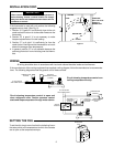
Circuit showing temperature control to open and
close refrigerant valve. Suction pressure control
starts and stops compressor through motor starter.
TEMPERATURE
CONTROL
HIGH SIDE
PRESSURE CONTROL
(IF USED)
TO LINE SWITCH
AND POWER SUPPLY
HOT
GND
Circuit showing temperature control con-
trolling compressor directly.
If the manufacturer of the cooling equipment has supplied a wiring diagram, follow the manufacturer’s recommenda-
tions. The following diagrams show the general use of these controls.
WIRING
All wiring should be done in accordance with local and national electrical codes and ordinances.
IMPORTANT
When control is located where ambient temperature is
below freezing, choose a control location far enough
away from doors and windows so that moisture will not
condense on control.
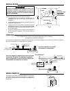
If the thermostat is used with unit coolers, the following
suggestions may help. (See Fig. 2).
1. Position “A” is good if it is sufficiently close to the unit
cooler so that the return air to the cooler flows over the
thermostat.
2. Position “B” is good if it is not necessary to make
frequent adjustments of the dial setting.
3. Position “C” is all right if it is sufficiently far from the
cooler that air flowing over the thermostat is not much
above the average room temperature.
4. In general, position “D” is not advisable because the
post may prevent air from circulating over the thermo-
stat.
A
C
D
B
CEILING
POST
RETURN AIR
FLOOR
UNIT
PARTITION
WALL OR POST
DIRECTLY
BEHIND UNIT
70
60
80
INDICATING
LINE
Figure 2