3
G
4
W
ON
Fan
Switch
Cooling
Anticipator
Heating
Anticipator
AUTO
RCY
24 VAC
120 VAC
Hot
Neutral
Heating
System
Cooling
System
Fan
Relay
Thermostat
Contacts
COOL
HEAT
System
COOL HEAT
Field Installed
Jumper
In “OFF” position
system switch breaks
both heating and
cooling circuits
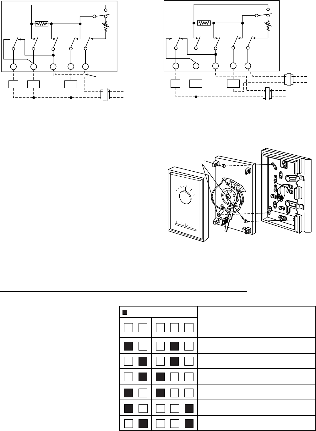
Figure 2. For installations where heating and
cooling systems are powered by the same transformer
24 VAC
120 VAC
Hot
Neutral
Heating
System
Cooling
System
Fan
Relay
24 VAC
120 VAC
Hot
Neutral
Cooling Transformer
Heating Transformer
G
4
W
ON
Fan
Switch
Cooling
Anticipator
Heating
Anticipator
AUTO
RCY
Thermostat
Contacts
COOL
HEAT
System
COOL HEAT
In “OFF” position
system switch breaks
both heating and
cooling circuits
Figure 3. For installations where heating system
is powered by a separate transformer
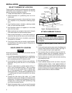
ATTACH THERMOSTAT TO SUBBASE
1. Remove cover from thermostat base by gripping the
base in one hand. Use the other hand to pull gently at
the top or bottom of the cover.
2. Carefully remove the shipping protective packing from
the switch.
3. Attach thermostat base to subbase, being sure that all
captive screws are tightened snugly, since they serve
as electrical connections between thermostat and
subbase (see fig. 4).
4. Snap cover on thermostat and set switches and tem-
perature lever to desired setpoint (see OPERATION
section).
5. Turn on power to the system.
Figure 4. Attach thermostat to subbase
Captive
screws
COVER
THERMOSTAT
BASE
S
Y
S
T
E
M
C
O
O
L
O
F
F
H
E
A
T
A
U
T
O
O
N
F
A
N
G
RC
Y
W
B
ARH
O
50
60
70
80
90
50
60
70
80
90
OPERATION &
MAINTENANCE
FAN
AUTO ON
SYSTEM
COOL OFF HEAT
Shows switch position
OPERATION
No heating; no cooling; no fan
No heating; no cooling; fan runs continuously
Cooling system cycles from thermostat; fan runs
continuously
Cooling system and fan cycle from thermostat
Heating system cycles from thermostat; fan cycles
from fan control on furnace
Heating system cycles from thermostat; fan runs
continuously
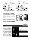
Figure 5. Subbase switching and thermostat/system operation
This thermostat is easy to operate. Fig. 5
shows how the heating/cooling system
and fan operate when the switches are in
various positions. Use the system switch
to select either heating or cooling, or to
turn the heating/cooling system off. Use
the fan switch to control fan operation.
When the fan switch is in the AUTO
position, the fan will cycle with the heating
or cooling system (the fan will not run if
the system switch is in the OFF position
and the fan switch is in the AUTO posi-
tion). When the fan switch is in the ON
position, the fan will run continuously,
regardless of system switch position (even
if the system switch is set to OFF, the fan
will run if the fan switch is in the ON
position).


