


8
Devices for Hot Water Supply Systems, ANSI Z21.22 -
latest edition. This valve must be marked with the maximum
set pressure not to exceed the marked maximum working
pressure of the water heater. Install the valve into an
opening provided and marked for this purpose in the water
heater, and orient it or provide tubing so that any discharge
from the valve exits only within 6 inches above, or at any
distance below, the structural fl oor, and does not contact
any live electrical part. The discharge opening must not be
blocked or reduced in size under any circumstance.
IMPORTANT: Only a new temperature and pressure relief
valve should be used with your water heater. Do not use an
old or existing valve as it may be damaged or not adequate
for the working pressure of the new water heater. Do not
place any valve between the relief valve and the tank.
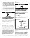
The Temperature & Pressure Relief Valve:
• Shall not be in contact with any electrical part.
• Shall be connected to an adequate discharge line.
• Shall not be rated higher than the working pressure
shown on the data plate of the water heater.
The Discharge Line:
• Shall not be smaller than the pipe size of the relief
valve or have any reducing coupling installed in the
discharge line.
• Shall not be capped, blocked, plugged or contain
any valve between the relief valve and the end of the
discharge line.
• Shall terminate a maximum of 6 inches above a floor
drain or external to the building.
• Shall be of material listed for hot water distribution.
• Shall be installed to allow complete drainage of both
the valve and discharge line.
Solar Installation
If this water heater is used as a solar storage heater or
as a backup for the solar system, the inlet water supply
temperatures to the water heater tank may be in excess of
120°F. A tempering valve or other temperature limiting valve
must be installed in the inlet water supply line to limit the
supply temperature to 120°F.
NOTE: Solar water heating systems can often supply water
with temperatures exceeding 180°F and may result in water
heater malfunction.
Water Heater Location
□ Centrally located with the water piping system.
□ Located indoors and in a vertical position. Protected
from freezing temperatures.
□ Provisions made to protect the area from water
damage. Metal drain pan installed and piped to an
adequate drain.
□ Sufficient room to service the water heater.
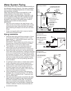
Water System Piping
□ Temperature and pressure relief valve properly
installed with a discharge line run to an open drain
and protected from freezing.
□ All piping properly installed and free of leaks.
□ Heater completely filled with water. (See Figure 2)
□ Closed system pressure buildup precautions
installed.
□ Tempering valve (when applicable) installed per
manufacturer’s instructions (see “Water Temperature
Regulation” section).
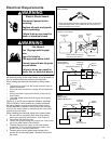
Electrical Connections
□ Wiring and connections comply with all applicable
codes.
□ Water heater and electrical supply are properly
grounded.
□ Proper overload fuse or circuit breaker protection
installed.
INSTALLATION
CHECKLIST