


ELECTRICAL CONNECTION
IMPORTANT: the data relevant to the voltage and power absorption are indicated on the rating plate.
ASSEMBLY
ADJUSTMENT TO DIFFERENT TYPES OF GAS
If the appliance is intended to operate with a different gas from the gas type stated on the rating plate and information label on the top of
the hob, change the injectors.
Remove the information label and keep it with the instructions booklet.
Use pressure regulators suitable for the gas pressure indicated in the Instruction.
• The gas nozzles must be changed by After Sales Service or a qualified technician.
• Nozzles not supplied with the appliance must be ordered from After Sales Service.
• Adjust the minimum setting of the taps.
NOTE: when liquid petroleum gas is used (G30/G31), the minimum gas setting screw must be tightened as far as it will go.
IMPORTANT: should you experience difficulty in turning the burners knobs, please contact the After Sales Service for the
replacement of the burner tap if found to be faulty.
REPLACING THE INJECTORS (see the injector table in the Instruction)
ADJUSTING MINIMUM GAS SETTING OF TAPS
REFERENCE TO LOCAL REGULATIONS
Regulation for room ventilation
NOTE: if the appliance is not equipped with safety devices on the burners (thermocouples), the air vents must be increased by 100%, and
must be at least 200 cm
2
), in compliance with M.D. 21 April 1993.
Connection to gas supply
Before connecting the appliance, make sure that the gas supply system complies with standards UNI-CIG 7129 and UNI-CIG 7131.
Gas connection
The connection to the mains gas network or gas cylinder must be made using a rigid copper or steel pipe with fittings complying with
standards UNI-CIG 7129, or using a continuous-surface stainless steel hose complying with standards UNI-CIG 9891.
The maximum length of the hose is 2 m.
The pressure control valves to be used must comply with the UNI EN 12864 standard for gas cylinders and the UNI EN 88 standard for piped
methane gas.
REFERENCE TO LOCAL REGULATIONS
Provision for ventilation
The room in which the appliance is installed must have an air supply to current B.S. 5440 - Part 2 standards.
All rooms require a permanent vent in addition to the openable window.
If there are other fuel burning appliances in the same room B.S. 5440 - Part 2 should be consulted to determine the air vent requirements.
If the appliance is installed in a cellar or basement, it is advisable to provide an air vent of 65 cm, irrespective of the room volume.
Gas Safety Regulations
The law requires that all gas appliances are installed by competent persons in accordance with the current gas safety regulations. Failure to
install appliances correctly may lead to prosecution.
It is in your own interest, and that of safety, to ensure that the law is complied with. The hob should be installed in accordance with the Gas
Safety (Installation and Use) Regulations, the Building Regulations issued by the Department of the Environment and the Building
Standard (Scotland) (Consolidation) Regulations, issued by the Scottish Development Department.
In the G.B., CORGI registered installers work to safe standards of practice.
AFTER-SALES SERVICE
WARNING
This operation must be performed by a qualified technician.
WARNING
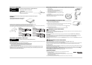
• The electrical connections must comply with
local regulations.
• The earthing of this appliance is compulsory by
law.
• Do not use an extension cord.
After having cleaned the perimeter surface, apply the
supplied gasket to the hob as shown in the figure.
Position the hob in the worktop opening made respecting the dimensions indicated in the Instruction.
NOTE: the power supply cable must be long enough to permit its upward extraction.
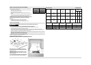
To secure the hob, use the brackets (A) provided with it. Fit the brackets into the relevant bores shown by the arrow and fasten them by
means of their screws in accordance with the thickness of the worktop (see the following figures).
WARNING
This operation must be performed by a qualified technician.
L
N
Earth
(yellow/green)
20
30
60
40
Top 20 mm Top 40 mm
Top 30 mm Top 60 mm
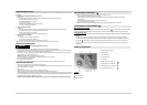
•Remove grids (A).
• Extract burners (B).
• Using a socket spanner of the appropriate size unscrew the
injector (C), unscrew the injector to be replaced.
• Replace it with the injector suitable for the new type of gas.
• Re-assemble the injector in (D).
• If you have a multiple crown burner use side spanner to replace
the injector (E).
Before installing the hob, remember to affix the gas calibration plate
supplied with the injectors in such a way that it covers the existing
information relating to gas calibration.
To ensure that the minimum setting is correctly adjusted, remove the knob and proceed as follows:
• tighten screw to reduce the flame height (-);
• loosen screw to increase the flame height (+).
The adjustment must be performed with the tap in minimum gas setting position (small flame) .
• The primary air of the burners does not need to be adjusted.
• At this stage, light up the burners and turn the knobs from max position to minimum
position to check flame stability.
Upon completion of adjustment, reseal using sealing wax or an equivalent material.
Before calling the After-Sales Service, make sure you can give the following information:
- type of fault or problem;
- exact model (written on the label affixed to the instruction/warranty);
- service number that follows the word SERVICE on the rating plate under the hob and on the label
affixed to instruction/warranty;
- your complete address and phone number.
If any repairs are required, please contact an authorised After-Sales Service, as indicated in the warranty.
IE