


4
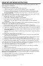
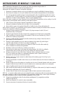
MOUNTING AND WIRING INSTRUCTIONS
NOTE: Underwriters Laboratories (UL) does not require all fixtures to have ground wires. These
fixtures meet all UL specifications.
Warning: This fixture is for indoor use only.
1. Turn off power at circuit box to avoid possible electric shock.
2. Attach mounting bar (A) to outlet box (B) with outlet box screws (C)
(not included)
.
3. If not pre-assembled; thread hex nut 1 (D1), lock washer (F), hex nut 2 (D2) and screw collar
(F) onto mounting nipple (E) making sure you leave at least 1/4 “ space between hex nut 1
(D1) and hex nut 2 (D2).
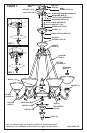
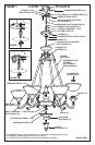
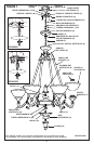
NOTE: Assemble the entire fixture on the floor. Be sure the canopy (T) (not shown to scale) and the
screw collar ring (R) are positioned on the chain (P) as shown in figure 1.
4. Spread fixture arms (G) to an equal distance apart.
5. Thread fixture column (H) onto nipple 1 (I1) (if applicable).
6. Attach support rod (J) to canopy hook (K) and to ring (L) on fixture arm (G).
7. Thread hex nut 3 (D3) onto nipple 2 (I2) and then thread nipple 2 (I2) into coupling (M)
(if applicable).
NOTE: It may be necessary, and is recommended, to use two people when attaching the fixture to the
mounting bar (A) and completing the wiring and adjustments.
8. Place decorative cap (N) over nipple 2 (I2) and secure with finial (O) (if applicable).
9. Open one link on bottom end of chain (P). Attach to fixture loop (Q). Securely close link on chain (P).
10. Thread screw collar ring (R) onto screw collar (S), then place canopy (T) over top of screw collar (S).
11. Lace wires up through every other link on chain (P) then up through screw collar (S), canopy (T)
and mounting nipple (E).
12. Open one link on top end of chain (P). Attach to loop on screw collar (S). Securely close link on
chain (P).
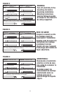
13. Identify color coding of fixture wires (see fig. 2).
14. To connect wires, take black fixture wire (group A from fig. 2) and place evenly against black
outlet box wire. Do not twist wires.
15. Fit wire connector (U from fig. 1) over wires and twist until there is a firm connection. If wire
connector (U) easily comes off, reattach and check again for a firm connection.
16. Repeat steps 14 and 15 with the white (group B from fig. 2) fixture wires and outlet box wires.
17. Partially thread green grounding screw (V) into side hole (W) on mounting bar (A) (see fig. 1).
18. Wrap ground wire from fixture around green grounding screw (V) leaving enough excess wire to
then connect ground wire and outlet box wire with wire connector (U), if applicable.
19. Tighten green grounding screw (V). Do not over tighten.
20. Remove screw collar ring (R) from screw collar (S) and secure screw collar (S) to mounting
nipple (E).
21. Tuck wires inside outlet box (B).
22. Raise canopy (T) to ceiling and secure screw collar ring (R) to screw collar (S) (see insert 2).
NOTE: If adjustment is necessary for proper canopy (T) fit, loosen hex nut 1 (D1) to raise fixture, or
loosen hex nut 2 (D2) to lower fixture. Lower or raise mounting nipple (E) accordingly and retighten
both hex nut 1 (D1) and hex nut 2 (D2).
23. Place glass shade(s) (X) over socket(s) (Y) and secure with retaining ring(s) (Z).
24. Install lamp(s). Do not exceed recommended wattage.
25. Turn power back on at circuit box.