


7
MOUNTING AND WIRING INSTRUCTIONS (SEMI-FLUSH)
FIXTURE ASSEMBLY INSTRUCTIONS
Warning: This fixture is for indoor use only.
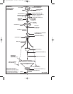
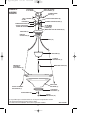
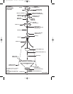
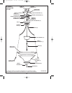
1. Remove top of cap (T) and remove cap nuts (U) from housing. Raise cap (T) up to mounting bar
(B) allowing mounting screws (P) to protrude through holes in cap (T), then secure with cap nuts
(U) (see fig. 2).
2. Thread hex nut (V) onto nipple (W) then thread nipple (W) onto coupling (X) (see fig. 2).
3. Install lamp(s). Do not exceed recommended wattage.
4. Raise glass shade (Y) up to fixture ring (H) allowing nipple (W) to protrude through center hole
in glass shade (Y).
5. Place decorative cap (Z) over nipple (W) then secure with round nut (Z1) and finial (Z2).
6. Turn power back on at circuit box.
NOTE: Underwriters Laboratories (UL) does not require all fixtures to have ground wires. These
fixtures meet all UL specifications.
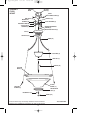
NOTE: This fixture can be mounted 2 ways: Pendant (see fig. 1) or semi-flush (see fig. 2). Follow
applicable mounting and assembly instructions below. Wiring instructions (see fig. 3) are the same for
both mounting options.
1. Turn off power at circuit box to avoid possible electric shock.
2. Thread mounting screws (P) into mounting bar (B) (see fig. 2).
3. Secure mounting bar (B) to outlet box (E) with outlet box screws (F) (not included). Mounting
screws (P) must protrude downward.
4. Spread arms (G) to an equal distance apart.
5. Secure fixture ring (H) to arms (G) with fixture screws (I).
6. Identify color coding of fixture wires (see fig. 3).
7. To connect wires, take black fixture wire (group A from fig. 3) and place evenly against black
outlet box wire. Do not twist wires.
8. Fit wire connector (Q from fig. 1) overwires and twist until there is a firm connection. If
wire connector (Q) easily comes off, reattach and check again for a firm connection.
9. Repeat steps 5 and 6 with the white (group B from fig. 3) fixture wires and outlet box wires.
10. Partially thread green grounding screw (R) into side hole (S) on mounting bar (B) (see fig. 1).
11. Wrap ground wire from fixture around green grounding screw (R) leaving enough excess
wire to then connect ground wire and outlet box wire with wire connector (Q), if applicable.
12. Tighten green grounding screw (R). Do not over tighten.
13. Tuckwires inside outlet box (E).
20 pg_W-050_EFS 4/7/05 10:53 PM Page 7