


4
NOTE: Underwriters Laboratories (UL) does not require all fixtures to have ground wires. These
fixtures meet all UL specifications.
1. Turn off power at circuit box to avoid possible electric shock.
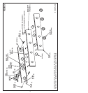
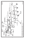
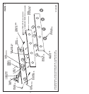
2. Beginning at sides and working at an angle, peel protective coating (if applicable) from face
plate (A) (see fig. 1).
3. Remove cups (B) from sockets (C) by simultaneously twisting and pulling cups (B) counter
clockwise off of sockets (C). If fixture is supplied with rings (R), unscrew counter clockwise
off of sockets (C).
4. Remove screws (D) and lock washers (E) (if applicable) from outer edges of face plate (A).
5. Separate decorative plate (F) (if applicable) and face plate (A) from back plate (G).
6. Push wires through back plate opening (H).
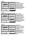
7. Identify color coding of fixtures (see fig. 2).
8. To connect wires, take black fixture wire (group A from fig. 2) and place evenly against
black outlet box wire. Do not twist wires.
9. Fit wire connector (I from fig. 1) overwires and twist until there is a firm connection. If wire
connector (I) easily comes off, reattach and check again for a firm connection.
10. Repeat steps 8 and 9 with the white (group B from fig. 2) fixture wires and outlet box wires.
11. Partially thread green grounding screw (J) into side hole (K) on back plate (G) (see fig. 1).
12. Wrap ground wire from fixture around green grounding screw (J) leaving enough excess
wire to then connect ground wire and outlet box wire with wire connector (I), if applicable.
13. Tighten green grounding screw (J). Do not over tighten.
14. Tuck wires inside outlet box (L).
MOUNTING AND WIRING INSTRUCTIONS
FIXTURE ASSEMBLY INSTRUCTIONS
Warning: This fixture is for indoor use only.
NOTE: For maximum support, secure back plate (G) with wood screws (M) (or plastic anchors
(N)) if outer holes (P) meet sheetrock by following steps 1 and 2 below.
1. Position flat side of back plate (G) against wall at mounting location and mark outer holes
(P) with a pencil.
NOTE: Back plate (G) must be level for fixture to hang straight.
2. Drill a 1/8” hole at each mark then insert plastic anchors (N) by gently tapping with a hammer.
3. Place back plate (G) over outlet box (L) and secure using outlet box screws (Q), not
included, and wood screws (M) (vertically or horizontally as desired, see fig. 1).
4. Position face plate (A) then decorative plate (F) (if applicable) over back plate (G) and
sockets (C).
5. Secure by simultaneously twisting and pushing cups (B) clockwise over sockets (C) (for a
tighter fit, slightly bend tabs inside cups (B) outward).
NOTE: If fixture is supplied with threaded sockets (C), thread rings (R) onto sockets (C).
6. Replace screws (D) (if applicable) and lock washers (E) (if applicable) on outer edges of face
plate (A).
7. Install lamp(s). Do not exceed recommended wattage.
8. Turn power back on at circuit box.