


Part Number 550-141-807/0298 5
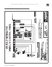
Flame Guardian WMBC-1A Electronic Pilot System – IRI
1. Size gas piping considering:
a. Diameter and length of gas supply piping.
b. Number of fittings.
c. Maximum gas consumption (including any possible future expansion).
d. Allowable pressure drop from gas meter outlet to boiler. For pressure drops, see ANSI-Z223.1 – latest
edition.
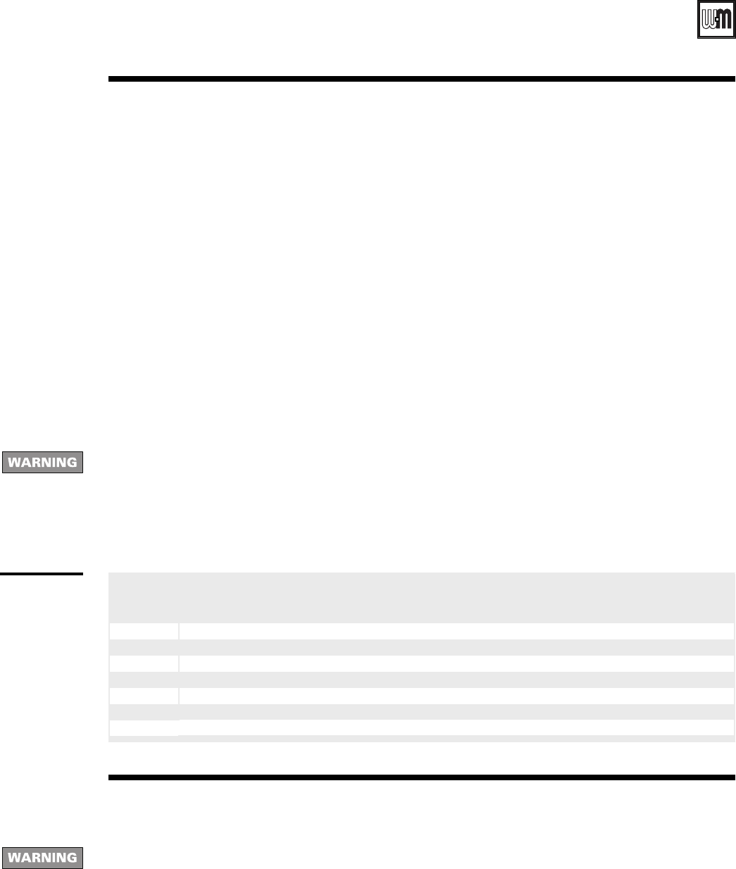
2. Size natural gas piping from table below. Size piping to provide proper inlet pressure to gas valve when operating
at rated input.
a. Inlet gas pressure to manual main shutoff gas valve minimum 7” W.C. standard (5½” on special order) –
maximum 13” W.C.
b. If pressure to gas valve exceeds 13” W.C., install positive dead-end lockup gas pressure regulator up stream of
hand valve.
c. To obtain approximate cubic feet per hour, divide input (BTU/HR) by 1000.
3. Remove gas supply knockout disc from jacket panel.
4. Follow good piping practices.
5. Pipe joint compound (pipe dope) must be resistant to corrosive action of liquefied petroleum gases. Apply
sparingly only to male threads of pipe joints.
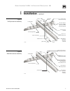
6. Install drip leg at inlet of gas connection to boiler. Where local utility requires, extend drip leg to floor.
7. Install ground joint union when required for servicing.
8. Support piping by hangers, not by boiler or its accessories.
9. Purge all air from supply piping.
10. Check all connections for leaks.
a. Close manual main shutoff valve during any pressure testing at less than 14.0 inches water column.
b. Disconnect boiler and gas controls from gas supply piping during any pressure test greater than 14.0 inches
water column.
11. Set gas pressure switches as follows or to local inspector’s requirements:
a. Low – 3.0” W.C. b. High – 14.0” W.C
II Gas piping
Do not check for gas leaks with an open flame – BUBBLE TEST. Failure to use bubble test or test for leaks can cause
severe personal injury, death or substantial property damage.
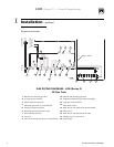
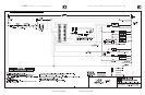
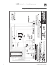
III Wiring
1. All wiring must be installed in accordance with the requirements of the National Electrical Code and any additional
national, state or local code requirements having jurisdiction. All wiring must be N.E.C. Class 1.
2. The boiler must be electrically grounded in accordance with the National Electrical Code, ANSI/NFPA No. 70-
latest edition. Use 105 °C. thermoplastic wire, or equivalent, if any of the original wire must be replaced (except
for pilot spark, sense and ground wires).
3. Supply wiring to the boiler must be No. 14 gauge or heavier. Install in conduit.
4. A separate electrical circuit with a fused disconnect switch (15 amp. recommended) should be used for the boiler.
For your safety, turn off electrical power supply before making any electrical connections to avoid possible electrical
shock hazard.
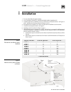
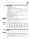
Table 2
Natural gas
supply pipe
sizing
PIPE
SIZE
10
’
20
’
30
’
40
’
50
’
75
’
100
’
150
’
1¼" 1,050 730 590 500 440 360 305 250
1½" 1,600 1,100 890 760 670 545 460 380
2" 3,050 2,100 1,650 1,450 1,270 1,020 870 710
2½" 4,800 3,300 2,700 2,300 2,000 1,650 1,400 1,130
3" 8,500 5,900 4,700 4,100 3,600 2,900 2,500 2,000
4" 17,500 12,000 9,700 8,300 7,400 6,000 5,100 4,100
* Include measured length of gas supply piping and allowance in feet for number and size of fittings.
PIPE LENGTH, FEET (NATURAL GAS CAPACITIES, LISTED IN MBH)
(Specific Gravity 0.60 @ Pressure Loss of 0.30" w.c.)