


13
Part Number 550-110-031/0605
Control Supplement — Standing Pilot Boilers
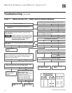
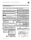
Troubleshooting
Verify proper operation after servicing
Never jumper (bypass) any device except for momentary
testing as outlined in troubleshooting chart below.
Substantial property damage and/or severe personal
injury could occur.
Burner access panel must be in position during boiler
operation to prevent momentary flame rollout on
ignition of main flame. Severe personal injury or
substantial property damage will result.
Label all wires prior to disconnection when servicing
controls. Wiring errors can cause improper and
dangerous operation leading to severe personal injury,
death or substantial property damage.
Before troubleshooting:
1. Have a voltmeter that can check 120VAC, 24VAC, and a continuity tester.
2. Check for 120VAC (minimum 102 to maximum 132) to boiler.
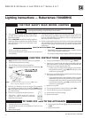
3. Be sure pilot is lit. See “Lighting instructions” on page 12 for details.
4. Make sure thermostat is calling for heat and contacts (including
appropriate zone controls) are closed. Check for 24VAC between
thermostat wire nuts and ground.
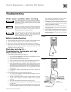
Pilot does not stay lit —
Troubleshooting thermopile and high
limit control circuit
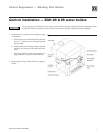
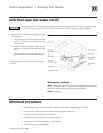
1. Checking thermopile open system (Figure 5):
a. Use an electronic multimeter, with leads fitted with alligator clips. Set
meter scale to DC Millivolts.
b. Unscrew thermopile fitting from gas valve.
c. Attach one meter lead to the end of the thermopile gas valve fitting.
d. Attach other meter lead to thermopile lead (copper surface).
e. Follow Lighting Instruction label on boiler (also found in Control
Supplement or User’s Information manual) to light the pilot burner
only and hold the pilot flame manually. (DO NOT light main burner.)
f. Check the reading on the multimeter. The reading should be around
700 millivolts.
g. If multimeter reading is significantly less than above, replace the
thermopile.
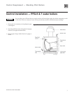
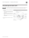
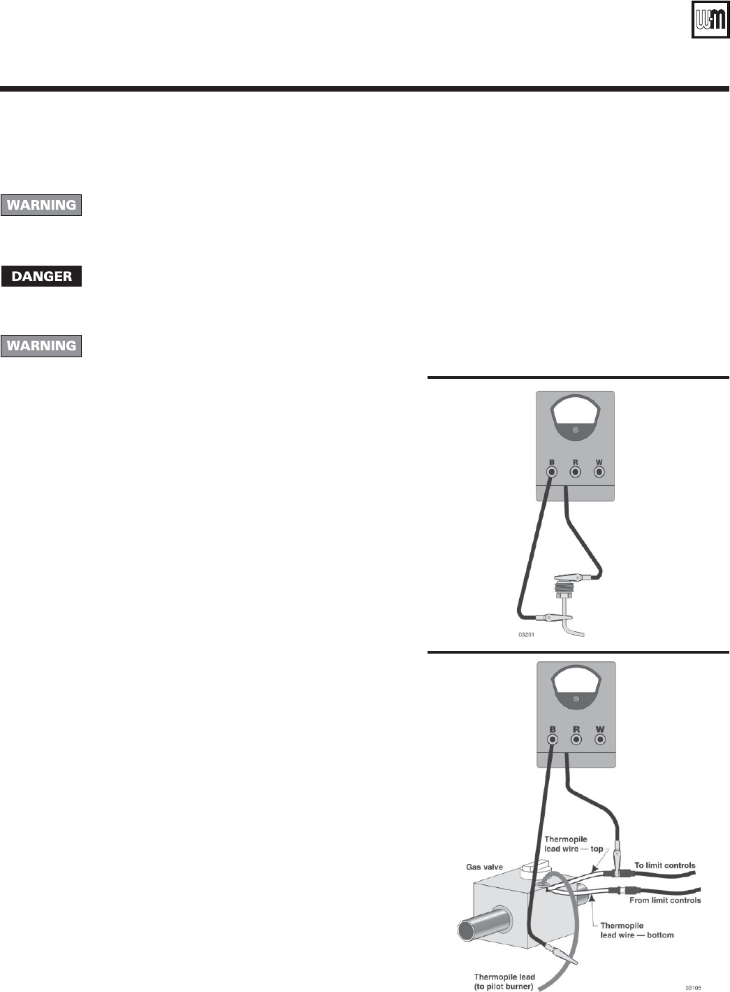
2. Checking thermopile circuit closed system (Figure 6):
a. Use an electronic multimeter, with leads fitted with alligator clips. Set
meter scale to DC Millivolts.
b. Loosen the insulated terminal on the TOP thermopile lead wire
enough to allow clipping a multimeter alligator clip to the spade
terminal.
c. Attach the other multimeter lead to the thermopile lead.
d. Check the reading on the multimeter. The reading should be around
400 millivolts.
e. If reading is significantly less than 400 millivolts, check tightness of
lead wire assembly in gas valve. If the connections are secure and you
Figure 5
Figure 6
have checked the thermopile per step 1 above,
replace the thermopile lead wire assembly.
f. If reading on TOP thermopile lead wire is around
400 millivolts, move the multimeter alligator clip
to the BOTTOM thermopile lead wire terminal
and check multimeter reading.
g. If multimeter does not read around 400 millivolts,
check wiring connections and wire integrity to
the limit controls.
h. Check voltage at each limit terminal to make sure
limit is closed. Correct pressure or temperature
condition causing any limit to be open. Replace
limit if necessary.