


Part number 550-101-233/0903
GAS-FIRED WATER BOILER — Boiler Manual
20
GAS-FIRED WATER BOILER — Boiler Manual
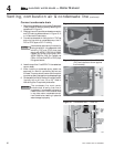
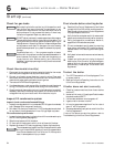
Connect condensate drain
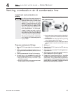
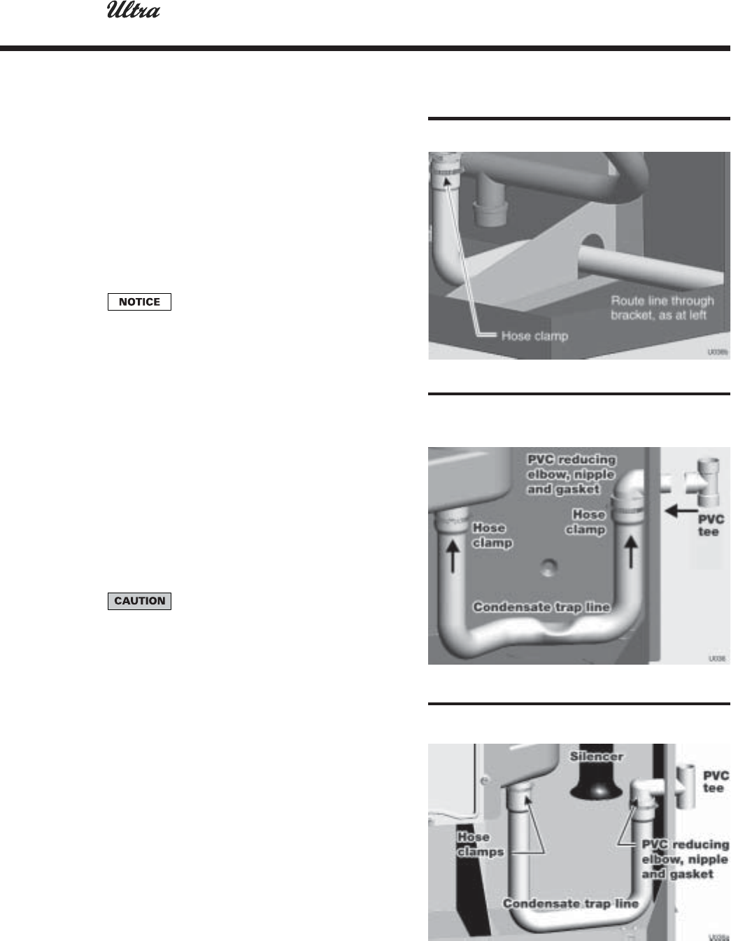
1. Remove condensate trap line from bag. Prepare and
install per page 19. Secure to jacket by attaching PVC
tee as shown in Figure 13.
2. Slide trap line onto flue outlet condensate connection
and PVC reducing elbow as shown in Figure 12, 13
or 14. Secure with hose clamps.
3. Connect condensate drain tubing to the ½" PVC tee
and run to floor drain or condensate pump. Use ½"
PVC or CPVC pipe; or 5/8" I.D. tubing.
Use materials approved by the authority
having jurisdiction. In the absence of other
authority, PVC and CPVC pipe must
comply with ASTM D1785, F441 or D2665.
Cement and primer must comply with
ASTM D2564 or F493. For Canada, use
CSA or ULC certified PVC or CPVC pipe,
fittings and cement.
4. Leave the top of the ½" tee OPEN. This is needed as a
vacuum break.
5. When installing a condensate pump, select one
approved for use with condensing boilers and
furnaces. The pump should have an overflow switch
to prevent property damage from condensate spillage.
6. Condensate from the Ultra boiler will be slightly acidic
(typically with a pH from 3.2 to 4.5). Install a
neutralizing filter if required by local codes.
The condensate line must remain
unobstructed, allowing free flow of
condensate. If condensate is allowed to
freeze in the line or if the line is obstructed
in any other manor, condensate can exit
from the boiler tee, resulting in potential
water damage to property.
Venting, combustion air & condensate line
(continued)
4
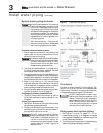
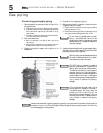
Figure 12 Condensate drain — Ultra-80 & -105
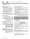
Figure 13 Condensate drain — Ultra-155 & -230
(PVC tee installation shown applies
to all models))
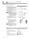
Figure 14 Condensate drain — Ultra-310