


GAS-FIRED WATER BOILER — Boiler Manual
Part number 550-101-233/0903
33
Maintenance — general
8b
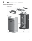
Replace boiler jacket front door after startup or servicing
Replace boiler jacket front door after start or servicing. The boiler front door must be securely fastened
to the boiler to prevent boiler from drawing air from inside the boiler room. This is particularly
important if the boiler is located in the same room as other appliances. Failure to keep the door securely
fastened could result in severe personal injury or death.
General maintenance
1. Oil motor in system requiring regular oiling.
2. See Oil bearing circulators for motor oiling
procedures.
Oiled bearing circulators
1. The circulator shipped with the Ultra boiler is water-
lubricated. No oiling is required.
2. Check other circulators in the system. Oil any
circulators requiring oil, following circulator
manufacturer’s instructions. Over-oiling will damage
the circulator.
Cleaning boiler heat exchanger
The boiler contains ceramic fiber materials.
Use care when handling these materials per
instructions on page 29 of this manual.
Failure to comply could result in severe
personal injury.
1. Shut down boiler:
a. Follow “To Turn Off Gas to Appliance” instructions on
boiler and Lighting instructions.
b. Do not drain boiler unless it will be exposed to freezing
temperatures. If using freeze prevention fluid in system,
do not drain.
2. Allow time for boiler to cool to room temperature if it has
been firing.
3. Remove jacket front door by removing two knurled head
screws at lower front. Lift door away from boiler to remove.
4. Follow procedure below to access the heat exchanger
interior.
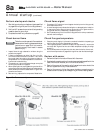
Access exchanger: Ultra-80 and Ultra-105 Only
1. Remove (4) Phillips-head screws securing gas valve
inlet adapter to gas valve. This will disconnect the gas
valve from the gas line.
2. Remove the air silencer by separating it from the air
adapter on the blower inlet.
3. Disconnect the gas valve plug, blower power supply
plug and blower control connector.
4. Release the exchanger cover plate by removing the
nuts securing it to the exchanger.
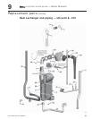
5. Pull the entire blower/venturi/gas valve/cover plate
assembly out of the boiler. (See pages 39 or 41 for
component identification and locations.)
6. Use a vacuum cleaner to remove any accumulation
on the heating surfaces. Do not use any solvent.
7. If the vacuum cleaner is unable to clean completely,
wash the heating surfaces with clean, warm water. If
necessary, use a piece of 20-gauge or lighter sheet
metal ¾" wide by about 18 inches long to loosen
deposits.
8. Inspect the heat exchanger cover plate insulation.
Replace if insulation is damaged. Read the ceramic
fiber WARNING on page 29 before handling or
disposing of ceramic fiber materials.
9. Re-install the blower/venturi/gas valve/cover plate
assembly and secure the cover plate with nuts.
10. Connect gas valve electrical plug and blower power
and control connectors.
Inspect the O-ring that should still be in
the gas valve inlet adapter block. The O-
ring must be in good condition and must
be installed when gas valve is reconnected.
Failure to comply will cause a gas leak,
resulting in severe personal injury or death.
11. Secure gas valve inlet adapter to gas valve with (4)
Phillips-head screws.
12. Re-install the air silencer by pressing onto the air
inlet adapter.
13. Install access cover gasket, chamber insulation
assembly and cover. Secure cover with nuts.
14. See continued instructions on next page.