


GAS-FIRED WATER BOILER — Boiler Manual
Part number 550-101-233/0903
13
GAS-FIRED WATER BOILER — Boiler Manual
Install water piping
(continued)
3
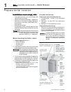
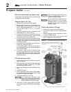
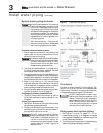
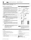
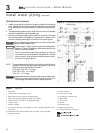
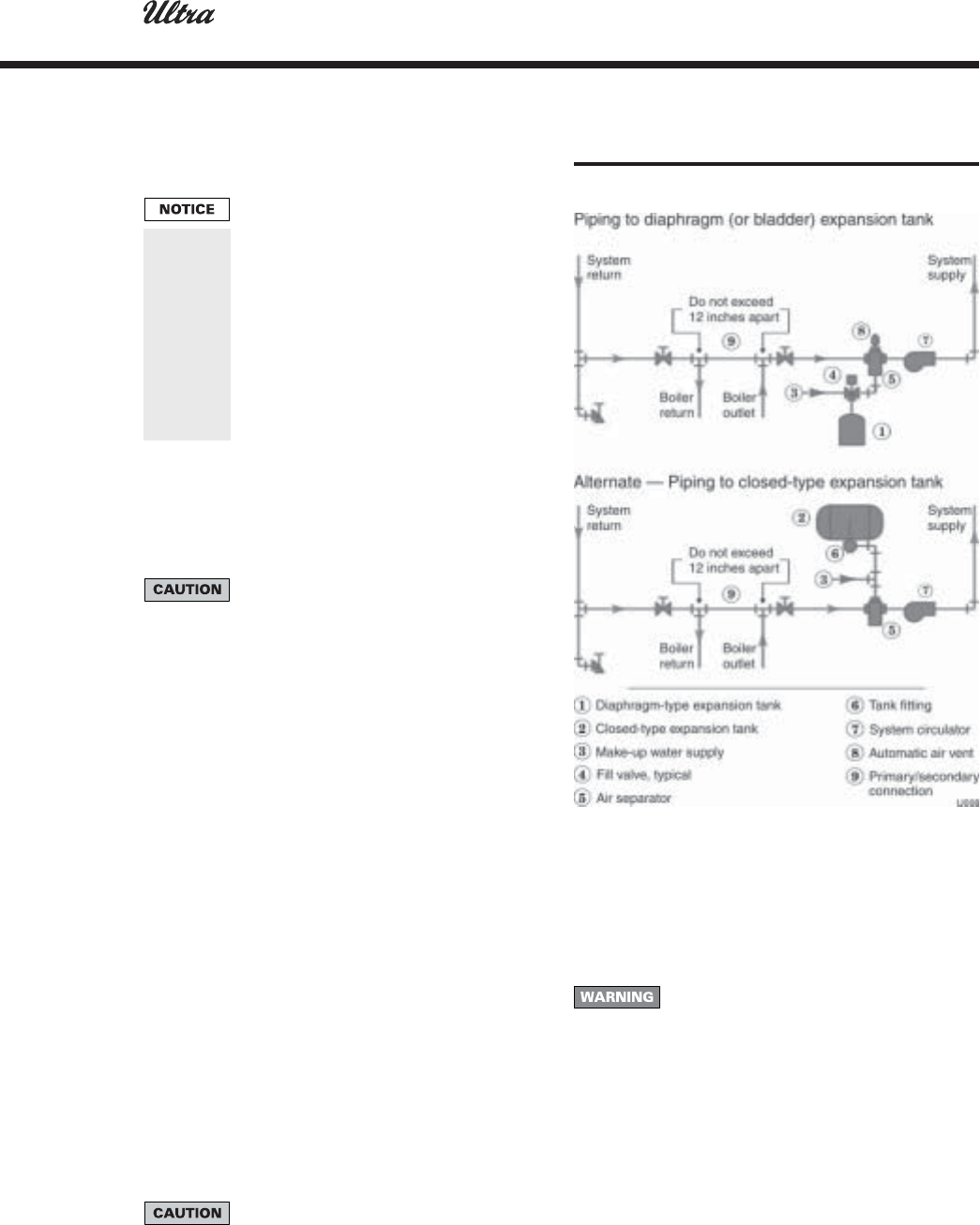
Figure 4 Expansion tank piping
System water piping methods
All piping methods shown in this manual
use primary/secondary connection to the
boiler loop. These designs ensure proper
flow through the Ultra boiler, for the most
efficient and reliable operation of the boiler
and the heating system. For other piping
methods, consult your local Weil-McLain
representative or refer to separate Ultra
boiler piping guides.
Wall-mounted boilers — Piping can exit
bottom of boiler enclosure. See separate
wall-mounting instructions for details.
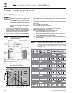
Circulators
The boiler circulator (Taco 007 for Ultra-80 and -105;
Taco 0011 for Ultra-155, -230, and -310) is shipped loose.
Locate it either in the return or supply piping, as shown
in the appropriate piping diagram in this manual.
DO NOT use the boiler circulator in any
location other than the ones shown in this
manual. The boiler circulator is selected to
ensure adequate flow through the Ultra
boiler. Failure to comply could result in
unreliable performance and nuisance
shutdowns from insufficient flow.
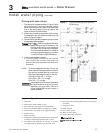
Sizing space heat system piping
1. See Figures 7 through 10, pages 15 – 18, for
recommended piping. In all diagrams, the space
heating system is isolated from the boiler loop by the
primary/secondary connection.
2. Size the piping and components in the space heating
system using recognized design methods.
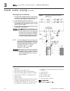
Expansion tank and make-up water
1. Ensure expansion tank size will handle boiler and
system water volume and temperature. Allow 3
gallons for boiler and its piping.
Undersized expansion tanks cause system
water to be lost from relief valve and make-
up water to be added through fill valve.
Eventual boiler failure can result due to
excessive make-up water addition.
2. Tank must be located as shown in this manual, or
following recognized design methods. See tank
manufacturer’s instructions for details.
3. Connect the expansion tank to the air separator only
if the separator is on the suction side of the circulator.
Always install the system fill connection at the same
point as the expansion tank connection to the system.
4. Most piping drawings in this manual show
diaphragm expansion tanks. See Figure 4 for piping
from air separator to expansion tank and make-up
water line using a closed-type expansion tank.
5. Most chilled water systems are piped using a closed-
type tank, as shown in Figure 10, page 18.
Diaphragm (or bladder) expansion tank
1. (Figure 4) Always install an automatic air vent on
top of the air separator to remove residual air from
the system.
Closed-type expansion tank
1. See Figure 4, Alternate, for piping connections when
using a closed-type expansion tank.
2. Pitch any horizontal piping up towards tank 1 inch
per 5 feet of piping. Connect to tank with at least ¾"
piping to allow room for air to rise.
DO NOT install automatic air vents on
closed-type expansion tank systems. Air
must remain in the system and return to
the tank to provide its air cushion. An
automatic air vent would cause air to leave
system, resulting in water-logging the
expansion tank.