


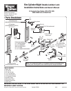

3
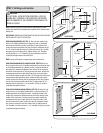
8000/8100/8200 DOORS, (SEE FIG. 4): Align the outside handle
assembly with the handle pointing towards the floor and insert the
assembly through the previously drilled 3/4” diameter holes in the
section. Secure the outside lock handle to the section with (2) #10
phillips head screws.
5120/5140/8300/8500/9700/9800/9100/9400/9600 & WOOD
DOORS, (SEE FIG. 5A & FIG. 5B): Align the outside handle assembly
with the handle pointing towards the floor and insert the assembly
through the previously drilled 3/4” diameter holes in the section. With
the outside lock placed in the section, place the center lock stile over
the shank of the outside lock handle, secure the center lock stile with
foam tape (8300/8500/8700/9700/9800 Series & Wood doors will
use the lock backup plate with no foam tape). Secure the outside lock
handle to the section by placing the (2) #10 phillips head machine
screws through the lock stile into the lock section.
NOTE: For 5140/9400 series doors, seal the v-groove with a bead of
clear silicone caulk.
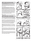
Hold the disk with the large notch of the release disk pointing up. Us-
ing 1/4” - 20 carriage bolts and nylon locking nuts, fasten lock bars to
disk. Do not overtighten nuts, bars must be free to rotate, (SEE FIG. 6).
First place the 3/8” x 1” washer over the square steel shank. Hold the
handle which is pointing towards the floor with one hand and place
the disk over the square steel shank of the outside handle. Push the
retainer nut onto the shank until the free play in the assembly is taken
up. Operate the lock to make sure it functions properly. If the lock
operates too hard, loosen the retainer nut slightly, (SEE FIG. 7).
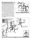
Place the inside handle over the extruded holes in the release disk,
(SEE FIG. 8). Secure the handle with (2) 1/4” - 20 x 1-3/4” self tap-
ping screws. Insert the rim cylinder through the trim ring and into the
section with the teeth side of the key pointing away from the outside
handle.
Place the lock plate over the 1-1/4”diameter center stile hole and
fasten with (2) #12 pan head screws into the rim cylinder. In addition,
align the night latch slide with the notch in the top of the release disk.
Fasten the night latch to the center stile with (4) #8 x 1/2” pan head
screws.
NOTE: Rotate the inside handle clockwise and tape the lock bar to the
section on both sides. Follow the Main Installation Instructions Manual
to install the remaining door sections and track. After the sections and
track are installed, continue with STEP 4.
Place
1st
lock
bar
Place
2nd
lock
bar
1/4” - 20 Nylon
locking nuts
1/4” - 20
Carriage
bolts
STEP 2: Outside Lock Handle Assembly
STEP 3: Inside Handle / Lock Assembly
Outside
handle
3/4” dia.
holes
#10 Phillips
head screws
Shank
Shank (out-
side handle)
Release
disk
Retainer
nut
3/8” x 1”
Washer
Release disk
Large notch
“up”
FIG. 4
FIG. 7
Lock
bar
Lock
bar
3/4” Dia.
holes
Outside
handle
#10
Phillips
head
screws
Handle
shank
Foam tape
Universal
lock stile
Foam tape
FIG. 5A
FIG. 5B
3/4” Dia.
holes
Outside
handle
#10
Phillips
head
screws
Handle
shank
Lock
backup
plate
FIG. 6