


Drum Installation
TORQUE TUBE
WINDING SHAFT
DRUM
TORQUE TUBE
LOOSE WINDING SHAFT
DRUM
WINDING
SHAFT GROOVE
ROUND
NOTCH
FLAG ANGLE
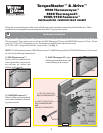
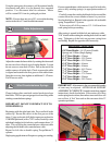
Shake the torque tube gently to extend the winding shafts
out about 5" on each side. For single spring applications,
there will be no left hand winding shaft in the torque tube.
Lift the torque tube and rest on top of flagangles. Orient
torque tube so that back of opener is flat against header/
spring pad. See Figure 12
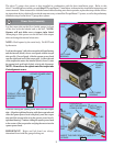
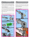
Cable drums and torque tube are cam shaped to fit together
only one way. To install the cable drum, slide the drum
over the winding shaft until the drum seats against the torque
tube. The winding shaft must extend past the drum far
enough to expose the splines and the groove. Align the
winding shaft groove with the round notch in the flagangle.
Repeat for opposite side.
NOTE: On single spring applications, take care in
handling the loose winding shaft (left side) so that it
does not slide back into the torque tube.
Single Spring Applications: Insert the left hand loose
winding shaft into the left hand drum prior to sliding the
drum over the torque tube.
FIG. 8
SPLINES
FIG. 6
FIG. 7
4
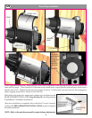
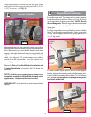
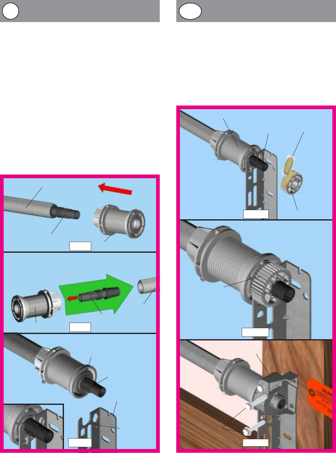
Drive Gear/End Bracket Installation
Ensure that torque tube is centered and level with door.
Beginning with the right hand side, lubricate entire
circumference of the drive gear with the oil provided in
the packet. Slide the drive gear onto the winding splines
until it touches the flagangles.
NOTE: No drive gear is required for the left side on
single spring applications.
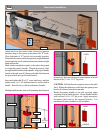
END BRACKET
FIG. 10
FIG. 9
DRIVE GEAR
OIL PACKET
DRUM
WINDING SHAFT
DRIVE GEAR
INSTALLED
(2) 1-5/8” LAG
SCREWS
FIG. 11
13
14a