


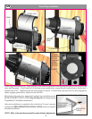
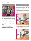
power head. With slack removed, secure bottom of handle
bracket with (1) 1/4 x 1-1/2" lag screw.
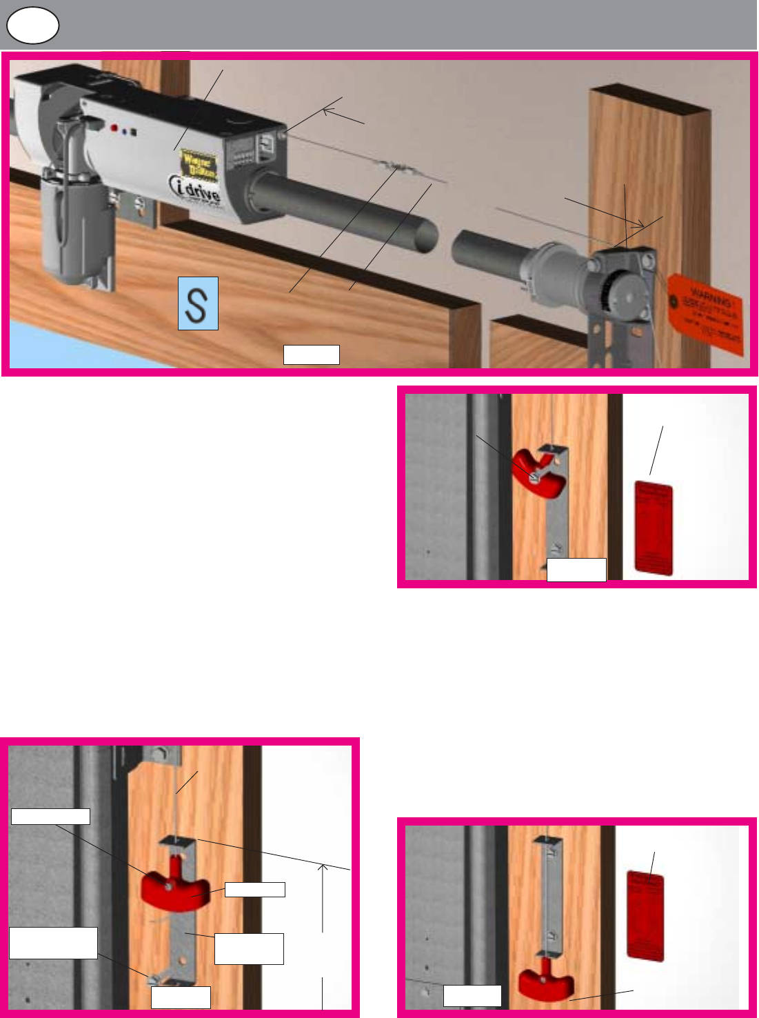
CAUTION: Pull handle just enough to remove the cable
slack. Pulling the cable more could cause the opener power
head to disconnect from the torque tube.
Rotate disconnect handle to one side exposing upper
mounting hole in handle bracket. Secure handle bracket
with a second 1/4 x 1-1/2" lag screw. Apply emergency
disconnect label next to the mounted bracket. Use
mechanical fasteners if adhesive will not adhere.
CABLE
1/4 X 1-1/2”
LAG SCREW
LABEL
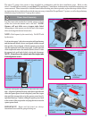
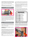
bracket with mark on wall. Remove all cable slack between
the power head and top of handle bracket.
Insert and tighten #6-20 x 1/2" screw until snug, and then
tighten screw 1 to 1-1/2 additional turns to secure cable in
handle. Trim off excess cable from bottom of handle.
Holding handle bracket, remove all remaining slack between
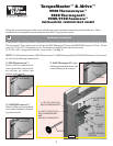
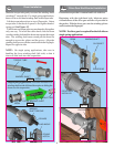
Attach the loose disconnect cable (located in operator
hardware bag) to the opener power head with “S” hook.
Close both ends of “S” hook to lock assembly together.
Thread the disconnect cable through hole in right hand end
bracket and remove all slack between power head and right
hand end bracket.
Mark location on right door jamb, six feet above the ground
to mount disconnect handle. Thread disconnect cable
through handle bracket and then handle. Align top of handle
Disconnect Installation
HANDLE
HANDLE
BRACKET
6’
(to bottom
of door)
#6-20 X 1/2”
1/4 X 1-1/2”
LAG SCREW
OPENER POWER
HEAD
END
BRACKET
HOLE
LOOSE
DISCONNECT
CABLE
REMOVE ALL SLACK IN CABLE
“S” HOOK
INSTALLED
FIG. 15
FIG. 17
FIG. 16
6
LABEL
HANDLE
FIG. 18
16a