


4
Remove the tape attaching the lock bars to the section. Using slot
#2, slide the required number of lock bar guides over the lock bars
with the mounting flange towards the center of the section. Lock
bars 5’ or less require (1) guide each and over 5’ require (2) guides
each. Position, as level as possible, the ends of the lock bars into
the square slots of the vertical track. Turn the inside handle coun-
terclockwise until the notch in the release disk aligns with the slide
of the night latch. Turn the key in the night latch to secure the lock
assembly. Verify the lock bar ends engage the vertical track slots.
Position the lock bar guides at the end of the section, 1/8” back from
the edge. Attach the lock bar guide to the end stile with (2) 1/4” - 20
x 11/16” self drilling screws each (WOOD DOORS use 1/4” - 20 x
1” lag screws). For lock bars over 5’, position the second lock bar
guide in the middle of the lock bar and secure the guide with (2)
1/4” - 20 x 11/16” self tapping screws each (WOOD DOORS use
1/4” - 20 x 1” lag screws). Unlock the night latch and turn the inside
handle clockwise. Hook the open loop of the release spring into the
slot of the right lock bar. Insert the 1/4” - 20 x 11/16” self drilling
screw through the closed loop of the release spring and secure it
into the lock backup plate hole below the lock assembly. Operate
the lock several times to make sure the lock bars move in and out of
the vertical track smoothly. Adjust the lock bar guides up or down, if
necessary, (SEE FIG. 9).
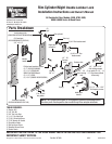
STEP 1: Installing The Lock bar Guides
“Notch” of
release disk
Release spring
Lock bar
Inside
Handle
Lock bar guide
(mounting
flange towards
center)
1/4” - 20 X 11/16” Self drilling
screws (2 per guide) (Wood
doors use 1” Lag screws)
“Slide” of
night latch
Slot #1
End
stile
Center stile
Vertical track
lock bar slots -
use the slot that
will level the
lock bar the best
Second lock bar guide required for
lock bars over 5’ in length.
(9100 Series will use extra stiles
and 1/2” screws).
FIG. 8
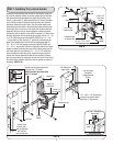
Rim
cylinder
Trim ring
Lock
plate
Night
latch
(4) #8 x 1/2”
Pan head
screws
(2) 1/4” - 20 x 1-3/4”
Self tapping screws
Extruded holes
in release disk
Inside
handle
Center stile
(2) #12 Pan
head screws
FIG. 9
Slot #2
1/8” Offset from
edge of door
End
stile
9700 Series only
Striker
plate
(2) 1/4” - 20 x 9/16”
Track bolts