


-2-
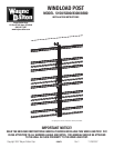
WIND LOAD POST
INSTALLATION INSTRUCTIONS
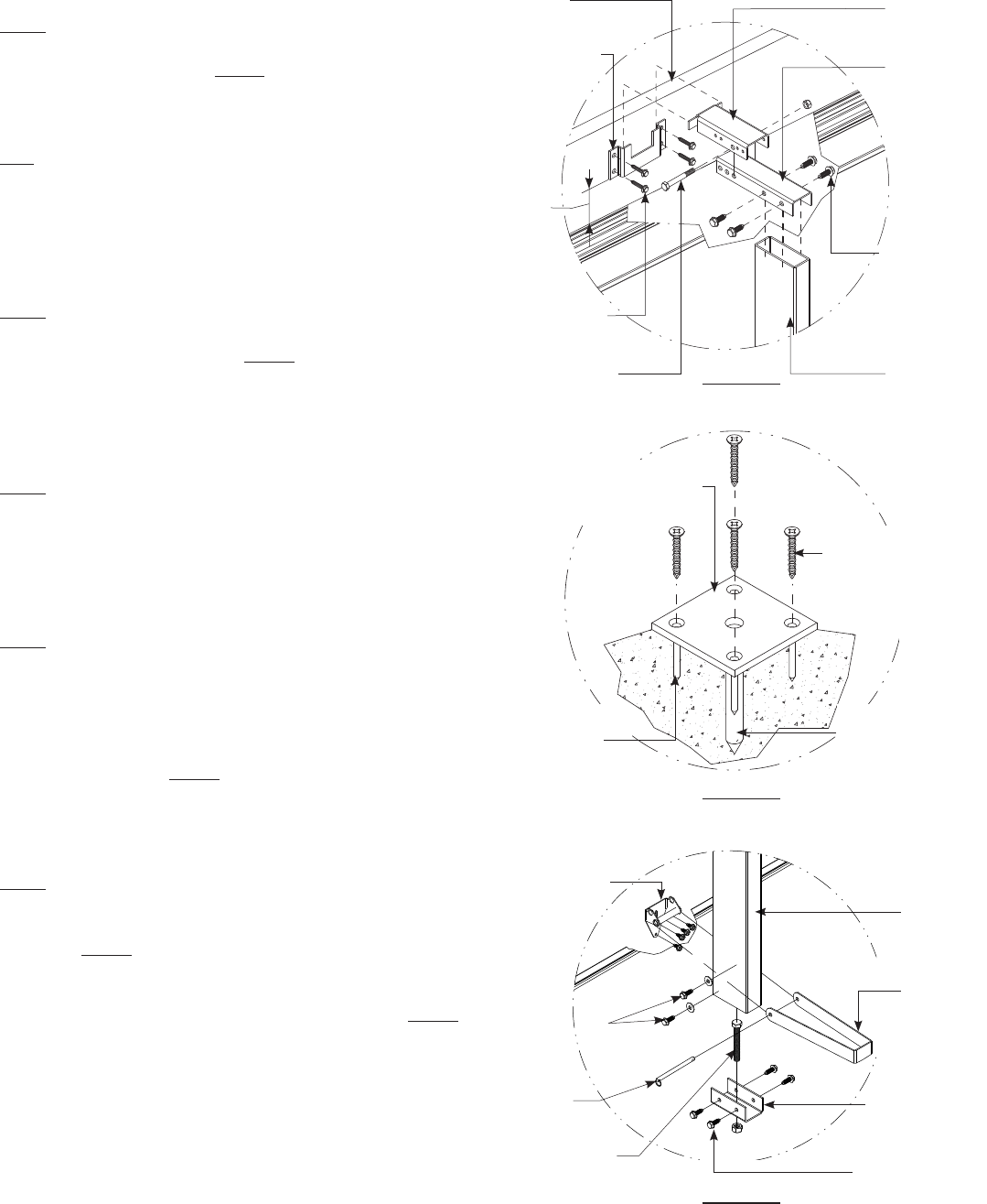
Step 1:
Attach the header lock bracket to the header using the (4) 5/16” x 1-5/8”
lag screws provided as shown in fi gure 1. The header lock bracket should
be in line with the intermediate hinges where the post is to be installed
and located such that the bottom of the bracket is approximately 2-1/2”
above the top of the door.
Note: drywall or any other sacrifi cial material covering the header must
be removed prior to installing the header lock bracket and replaced with
the same thickness of wood. If this process is required, the length of
the lag screws must be increased accordingly to include the thickness of
the wood so that a minimum of 1-1/2” of lag screw penetration into the
header is maintained.
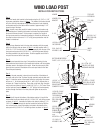
Step 2:
Align the large diameter hole in the top plate extension with the second
hole in the top lock plate as shown in fi gure 1 and bolt together with (1)
5/16-18 x 2-1/2” hex bolt and nut. Align the assembly over the top of the
inner post and secure with (4) 5/16-12 x 1” self drilling screws through
the holes provided in the top lock plate. Slide the opposite end of the in-
ner post into one end of the outer post.
Step 3:
Place the post assembly from step 2 into position by lowering the top
plate extension into the notch in the header lock bracket until the top plate
extension seats in the bottom of the notch. Allow the outer post to slide
down the inner post until the bottom of the outer post rests on the fl oor.
Plumb the post assembly.
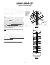
Step 4:
Ensuring the post assembly is plumb, trace the outline of the bottom of
the outer post on the fl oor. Remove the post assembly and set aside until
step 5. Locate the center of the traced outline by connecting the corners
to form an ‘x’. At the intersection of the ‘x’, drill a 9/16” diameter hole a
minimum of 4” deep into the fl oor. Clean dust out of hole. Align the plate
over the hole as shown in fi gure 2 and drill (4) 3/16” x 1-3/4” holes. Clean
out the holes and insert the (4) 1/4” x 1-3/4” phillips fl at head masonary
anchors through the holes in the fl oor plate and tighten to secure the
plate.
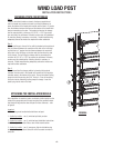
Step 5:
Place the half hinge at the bottom of the bottom section in line with the
intermediate hinges and attach with (4) 1/4-20x11/16” self drilling screws
as shown in fi gure 3. Assemble the bottom lock plate by sliding (1) 1/2-
13x3-1/2” bolt down through the top the bracket and securing with the
hex nut from below. Attach the bottom lock plate to the bottom of the
outer post with (4) 5/16-12x1” self drilling screws as shown in fi gure 3.
FIGURE 3
FIGURE 1
HEADER
HEADER LOCK
BRACKET
TOP PLATE
EXTENSION
TOP LOCK
PLATE
2-1/2”
(4) 5/16x1-5/8”
LAG SCREWS
5/16-18x2-1/2”
HEX BOLT & NUT
(4) 5/16-12x1”
SELF DRILLING
SCREWS
INNER
POST
5/16”
HITCH PIN
(2) 5/16-12x1”
SELF DRILLING
SCREWS W/ 5/16
FLAT WASHERS
BOTTOM
LOCK PLATE
(4) 5/16-12x1”
SELF DRILLLING
SCREWS
OUTER
POST
LOCKING
STRAP
1/2-13x3-1/2”
HEX BOLT & NUT
14 GA NO. 2 HALF
HINGE ATTACHED
TO DOOR WITH
(4) 1/4-20x7/8”
SELF DRILLING
SCREWS
FIGURE 2
(4) 1/4” x 1-3/4”
PHILLIPS FLAT HEAD
MASONARY ANCHOR
(1) 9/16” x 4” DEEP
HOLE DRILLED INTO
CONCRETE FLOOR
(4) 3/16” x 1-3/4”
DEEP HOLES
DRILLED INTO
CONCRETE FLOOR
BOTTOM REINFORCING
PLATE 3-1/2” x 3-1/2” x 1/4”